Firstly, an apology, this was meant to be a much longer article about multimeters and using them to test the components of a motorcycle electrical system. But, I have run out of both time and space in this issue to fit it all in, so, instead, this will just be a shorter article introducing you to multimeters.
Electrics are often a tricky subject, because unlike mechanical systems where you can usually actually see things working, you can’t see the little electrons flowing through the cables. Multimeters are a useful tool that can be give you a visual indication of what is actually happening in electrical circuits.
When you start searching for a meter, you will find that there is a bewildering array, ranging from £3 up to hundreds of pounds. In days gone by, you would also have had the choice between an analogue meter (needle swinging over a scale) or a digital version. Digital meters used to be expensive, but such is the progress in the electronics world, they are now the cheapest option. (I looked on CPCs website - a good source for electrical/ electronic items - and they now only list one analogue meter. www.cpc.co.uk ) The choice you will have now is between a manual or auto-ranging meter.
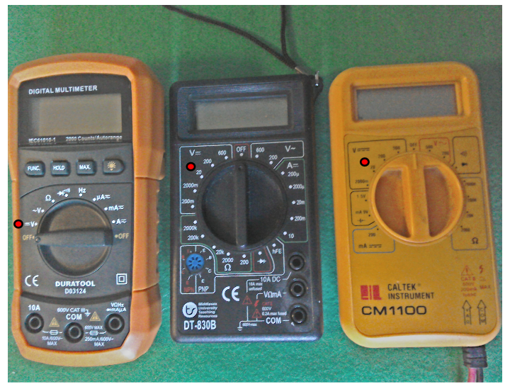
If you take a close look at the meters shown below, you will see that they all have rotary switches in the centre. These are used to select the function that you require, voltage, current, resistance etc. The two on the right have much more crowded dials. With these, you have to select what property you want to measure and what range, determined by what you think the maximum value will be. For example, let’s assume that you want to measure the voltage of your motorcycle battery. You expect it to be around 12 Volts (unless you have a 6 Volt bike!) and it’s going to be dc. I’ve put a red dot on where the switch would need to be on all three meters for you to safely measure this voltage. The meter on the left is auto-ranging, you only have to select dc voltage, and providing you don’t connect to something outside its measurement range, it will sort itself out. So, auto-ranging meters are a little easier to use, but do cost a little more.
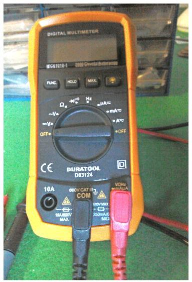
Here’s a closer look at the auto-ranging meter. I bought this one recently from CPC for £12 delivered and it has all the functions you are likely to need for basic motorcycle electrics. At the very minimum, a meter would need to measure voltage (dc and ac) and resistance. Other desirable features would be a continuity tester and ac / dc current. This meter has all those functions, plus it also has a built in stand and a rubber cover. Very useful as you will probably drop it at some time!
There are meters available with many other additional functions, and as they’ll cost you more, you need to decide whether you’re likely to use them. Most of these features will only be of real use if you start delving into electronic circuitry.
Meters usually come with test probes of the pointy end variety. If you can find a meter that comes with crocodile clip leads (or buy / make separate croc clip leads) you will find them useful. Being able to clip the leads in place will leave your hands free, if only so that they are available to catch the meter when it slips off whatever part of the motorcycle you had it precariously balanced on!
One last thing, if you buy a meter, it will come with a small user manual. Read it!
Next time we will look at actually using the multimeter.

This time we’re going to look at actually using the multi-meter, and we’ll start with one of its simplest functions, using the continuity test function to check the operation of switches.
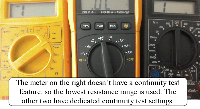
Most digital multi-meters have a dedicated setting for this type of test. It may often be combined with the diode test function (more of this later). If it doesn’t, you can use the lowest resistance range. The continuity function usually has a buzzer so that you can also hear when connection is made. This is useful when the component you’re trying to test is still on the bike. You’ll probably find that it’s hard enough keeping the probes in the correct place without having to also try and position the multi-meter so that you can see it! See picture, below, for typical multi-meter settings.
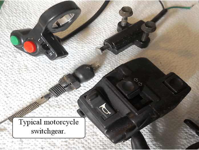
In picture below there’s a selection of switches that you might find on a motorcycle. It includes: the left hand switch gear from a CBF125, some generic Chinese aftermarket switch gear, and the brake light switch and side stand switch from a GS500. We’ll start with the brake light switch as it’s the easiest one to test. The side-stand switch should also be easy to test, it only has two wires after all, but this one is a little awkward, so we’re going to leave it until last.
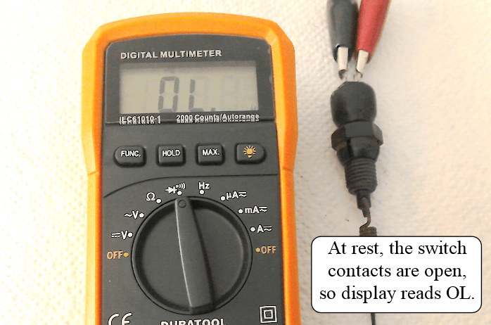
Anyway, back to testing the brake light switch. The first thing you need to do with this type of test is to isolate the bit that you want to check i.e. unplug it from the wiring loom! Next, connect a multi-meter lead to each of the two terminals. In this case it doesn’t matter which lead goes to which terminal. (See picture below.) This switch is normally open, so at rest, if you haven’t got your foot on the brake pedal pulling the spring and plunger down, there will be no connection between the two terminals at the top. The meter displays OL for overload because no current can flow as the circuit is not complete.
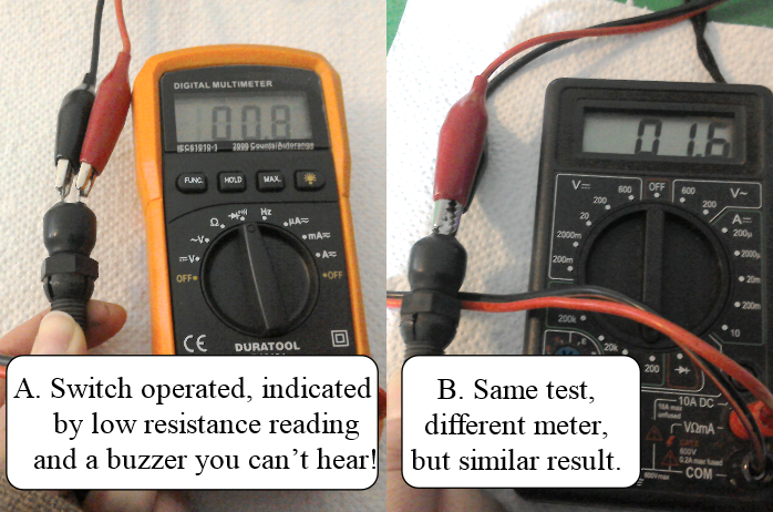
If you operate the switch (picture A below) the display changes to show the resistance between the two terminals is now 0.8 ohms. If you could hear what is going on, you’d also hear the buzzer. (You can do the same test using the meter set on the lowest resistance range – see picture B below). Any reading in single figures (i.e. below about 10 ohms) usually means everything is OK.
So that’s it, brake light switch checked and working. So, if your brake light still isn’t working, you need to look elsewhere for the fault! You can also check wiring in the same way. Connect a meter lead to each end of the wire you want to check (again make sure you’ve isolated it from other electrical circuits on the bike) if the buzzer doesn’t buzz, then you’ve got a broken wire or dodgy connector somewhere.
Next we’ll try the CBF125 switch gear. There are three switches we can test here: A push-button switch that selects dip or main beam. This is a latching switch i.e. you push it in, it stays in, you push it again, it comes out and stays out. There’s another push-button switch for the horn. This is a momentary switch i.e. it only operates when you’re physically pressing it. And finally, a slide switch for the indicators. This is another type of latching switch i.e. when you slide the switch to activate either the left or right indicators, the switch button itself will return to the centre, but the switch will stay connected until you push the button to turn it off. The switch connection diagram is shown below. Look back to Issue 5, if you can’t remember how to read these diagrams.
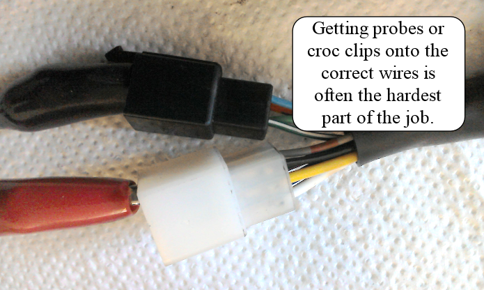
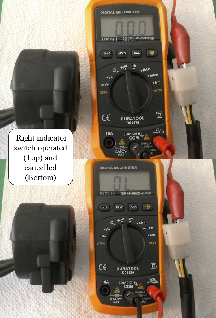
We’ll start with the turn signals. In the off position (N), nothing is connected. If we push the switch to the right, it should connect the Lb (Light Blue) and Gr (Grey) wires. See picture below. One of the wires is in the black plug, the other in the white. The next two pictures show the switch operated (top). Note the low resistance on the display (sadly you can’t hear the buzzer). Bottom picture shows the switch after the button has been pushed to turn it off. It now shows OL, indicating that there is no connection. To test the left indicators, you need connect one meter lead to the Gr (Grey) wire as before, and one to O (orange).
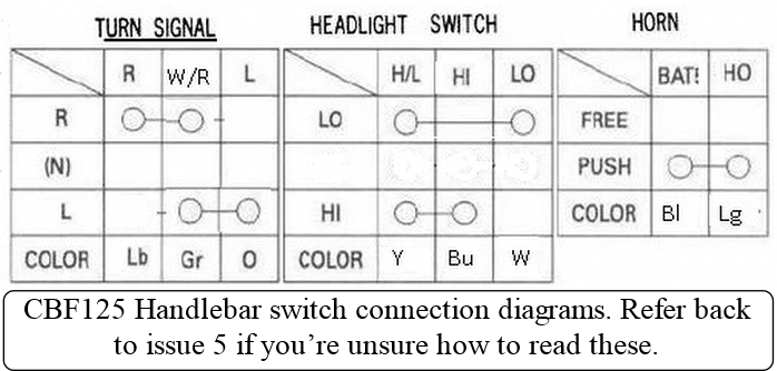
The horn switch is tested by finding the Bl (Black) and Lg (Light Green) wires and connecting the meter leads. When you press the button, your meter should buzz.
Finally we can test the headlight switch. This just toggles between dip and main beam. With the switch in the out position (dip) the Y (yellow) and W (white) wires will be connected. With the switch pressed in (main beam) the Y (yellow) and B (blue) wires will be connected. So, it’s a case of connecting your meter leads to the appropriate wires and operating the buttons to check for continuity as required.
Now for a look at the Chinese switchgear (see picture below); on first inspection it looks like it should perform all of the same functions as the Honda set. This set didn’t come with any instructions. The only info available was the little that was included in the ebay advert. Which was as follows:-
Blue –Lights
White – Horn
Green – Right turn
Yellow – Left turn
Red – Turn signal ground
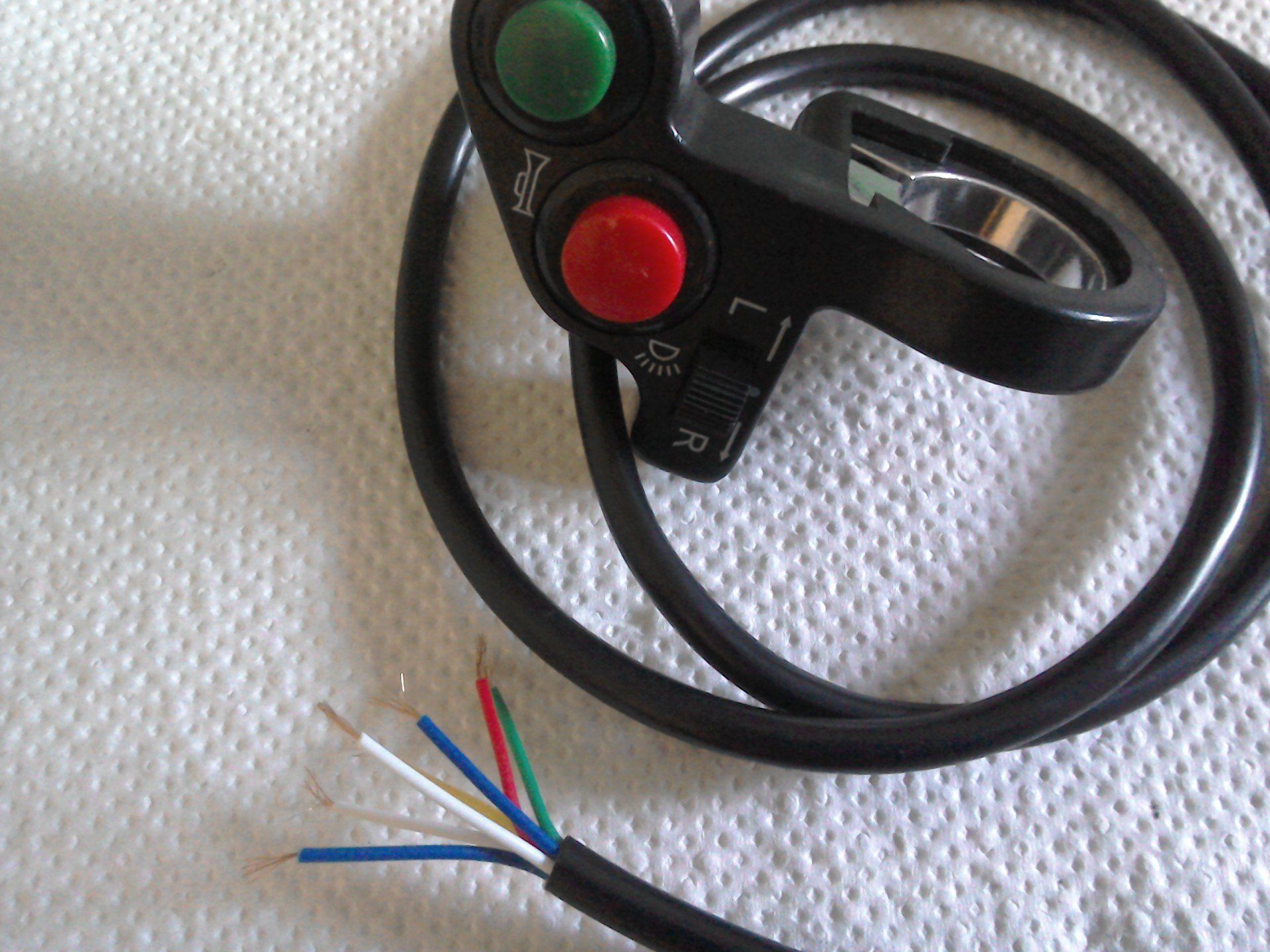
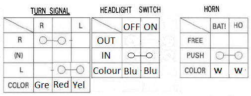
Inspecting what arrived, there turns out to be two blue and two white wires. The two blue ones are wired to the light switch. Connecting the meter leads, one to each blue wire, reveals that when the button is pressed in (it’s a latching switch, so it stays in until you press it again) the two blue wires are connected. When it’s out, there’s no connection. So, although it presses in and out like the Honda switchgear, it doesn’t do the same job. The Honda switch had three wires connected to it, a yellow wire which was common to both switch settings, operating the switch then connected this to either white or blue, depending on the switch position. The Chinese headlight switch only has two connections, and as it stands, could only turn a light on or off. This also means that you couldn’t do a straight swap between the Honda switchgear and the Chinese switches. There are other reasons why it might not be desirable to use the Chinese switches. That is outside the scope of this article, but will be covered in due course.
Horn and indicator switches are much the same as for the Honda gear. The horn switch is again a momentary type. Connect your meter leads to the two white wires and when you press the switch, you should get continuity.
Finally the indicator switch. This is a slide type, but unlike the Honda switch gear, it stays either to the left or right side as selected until you slide it back to the central position. To test it, connect one meter lead to the red wire and the other to either the green or yellow wire, depending on which switch position you want to check.
Below is a switch connection diagram for this switch that I’ve drawn for reference.
So that’s it. You should be able to test most of the switches on your bike. The hardest bit is usually working out which wires you need to connect to, and that usually means deciphering a wiring diagram or switch connection diagram.
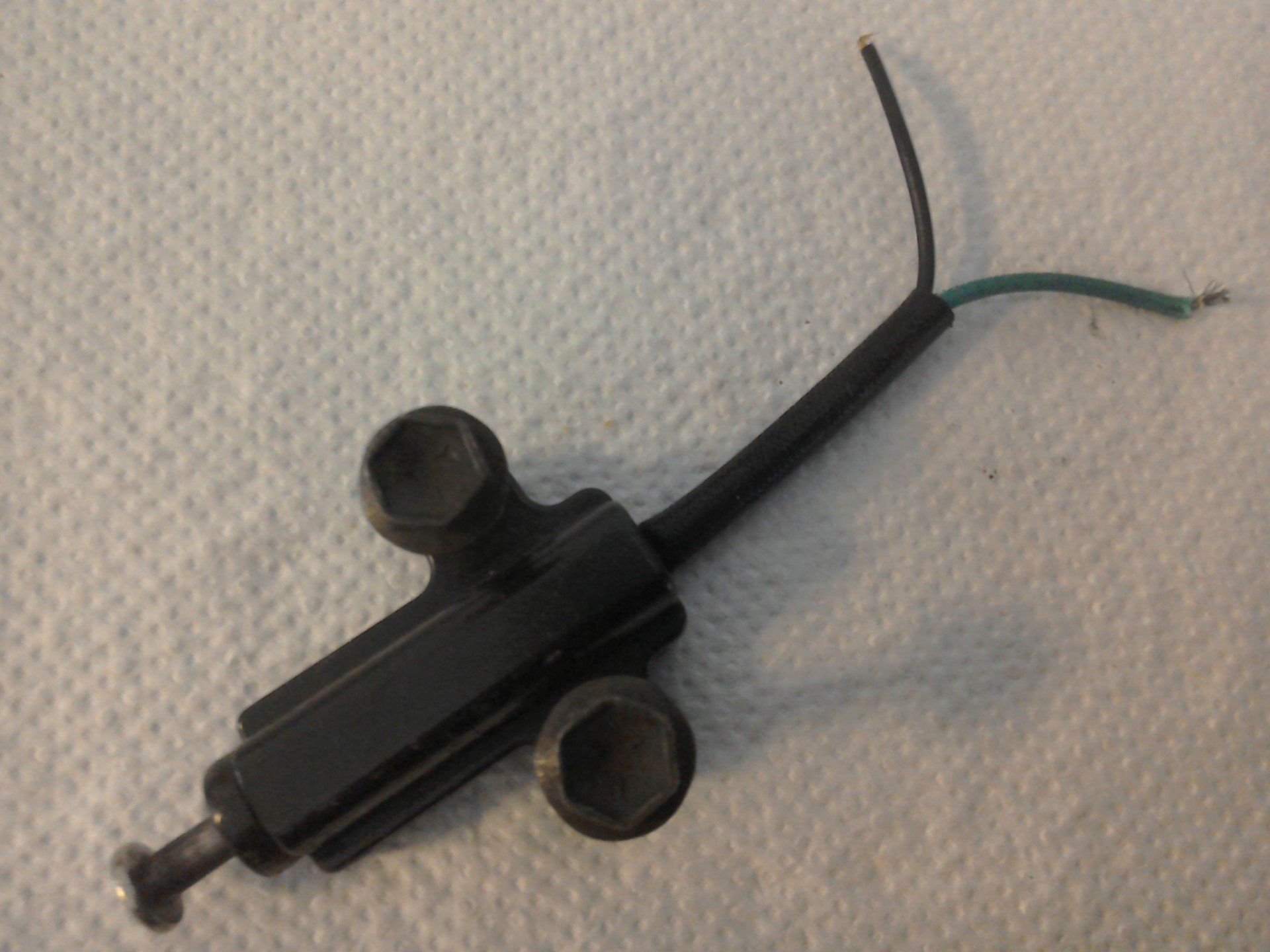
But now, let’s go back to the side-stand switch (pictured below).
The switch connection diagram is also shown below. Both my Haynes manual and the Suzuki manual indicate that this can also be tested with a simple continuity check. So I duly connected my meter leads and operated the switch, but no buzzer sounded. Did I have a defective switch?
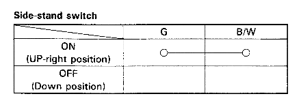
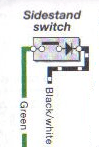
A closer look at the wiring diagram actually showed that the switch also includes a diode. See extract from wiring diagram (right). The diode symbol is a triangle/arrowhead with a line across the top.
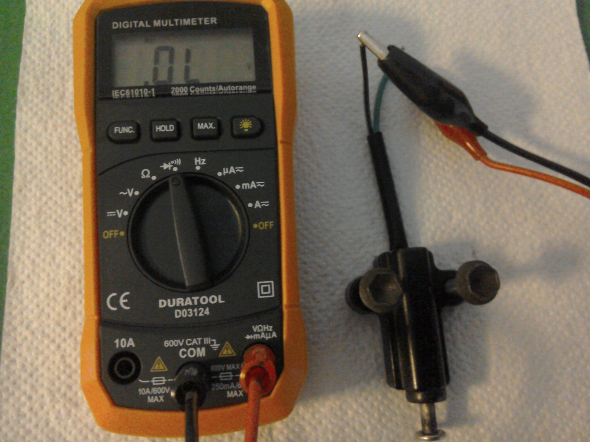
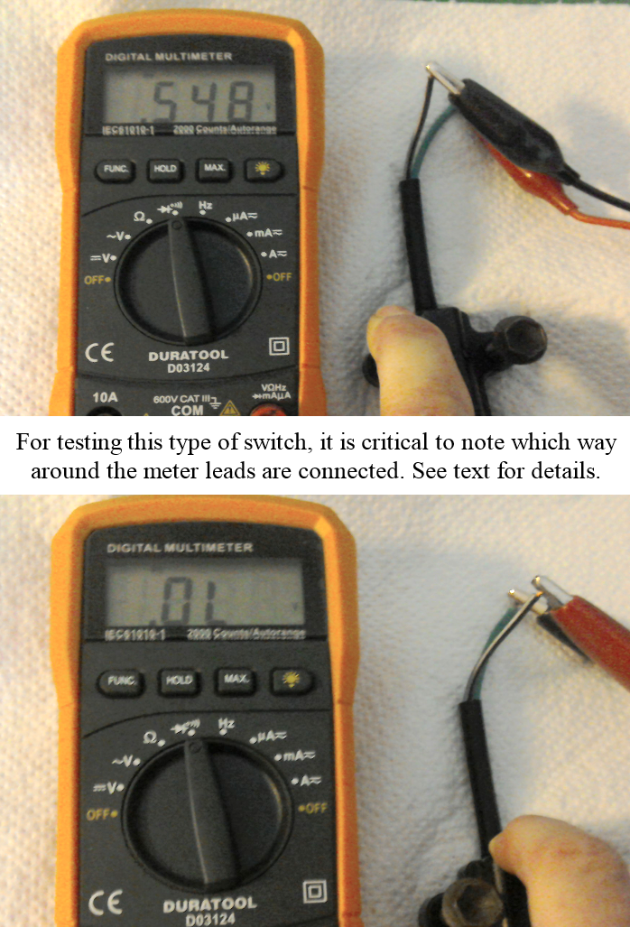
This diode is important. It only allows electrical current to flow one way (in the direction of the arrow of the diode symbol) but only when the voltage applied across it is greater than around 0.6V. It also means that the best way to test this is not with the continuity test function of the meter, but with the diode test function. This may have its own setting on your meter, but it is often incorporated with the continuity test function. On the Duratool meter I have, the function key is used to toggle between the diode or continuity test function. It is now also important to note which way around the meter leads are connected, since the meter uses its internal battery to supply a voltage across the diode to check its operation. When the COM lead (the black one) of the meter is connected to the black/white wire of the side-stand switch, and the red meter lead to the green wire, the
display should read OL (picture below). Operating the switch gives a reading of around 0.5V (picture below). This reading indicates the forward voltage that needs to be applied to the diode in order to make it conduct. If you get a reading between 0.5V and 0.8V this means that everything is Ok. If you reverse the meter connection (again, see below) and press the switch, the display should read OL because you’re now trying to make current flow the wrong way through the diode. If you get a reading of OL or 0V when the switch is pressed for both connection orientation, then you probably have a faulty diode.
And that’s quite enough about multi-meters and wiring for the moment.
