January 2019
Progress with the engine mounts has been slowed considerably by the Christmas holidays. Lack of garage time meant that I’ve only managed to (nearly) finish one of the two brackets required for the front mounts. I've used some 90 degree aluminium angle, mostly because I just happened to have some left over from another project. I'm not sure that these will be the permanent solution, but they'll do the job for the moment.
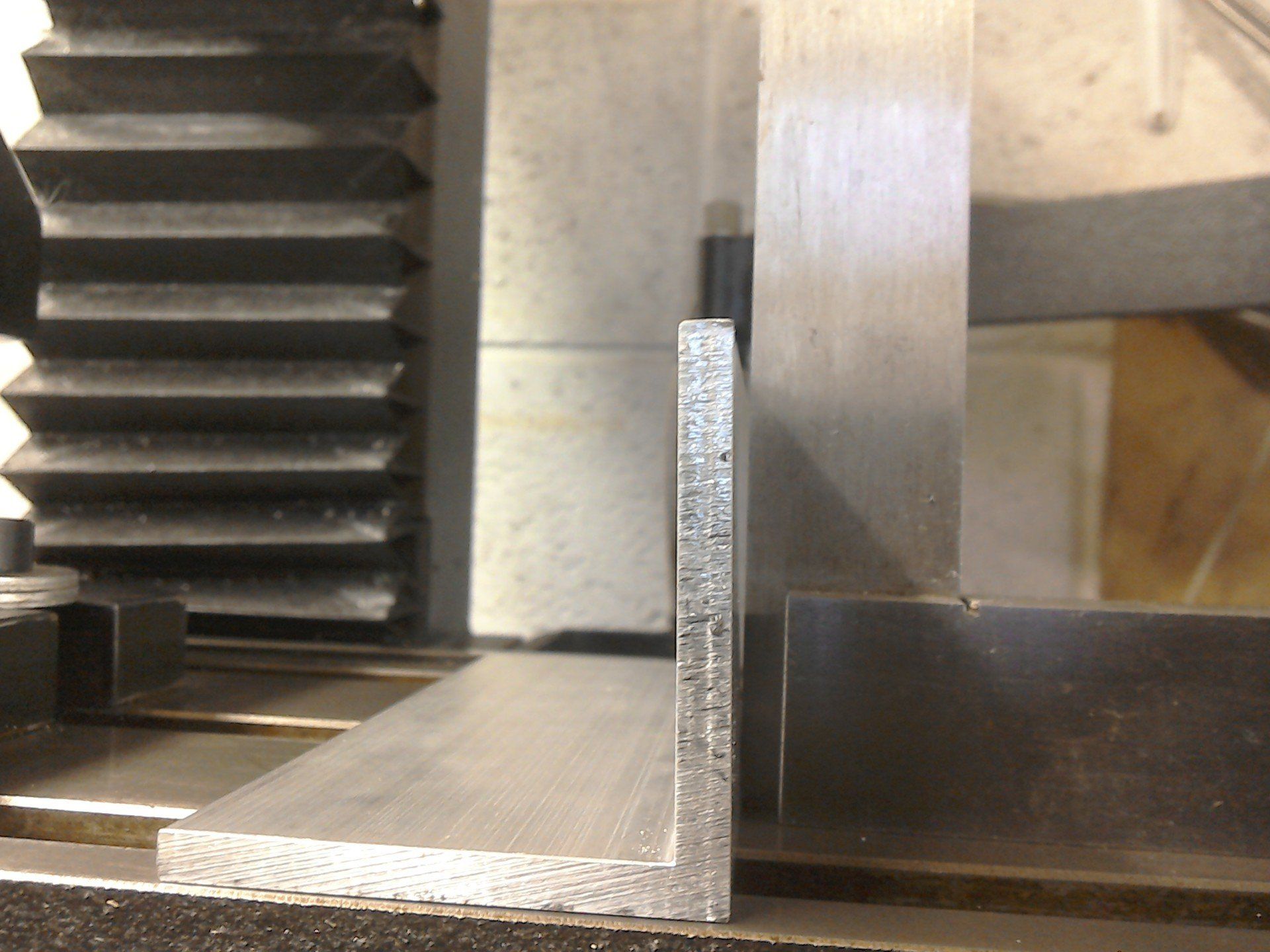
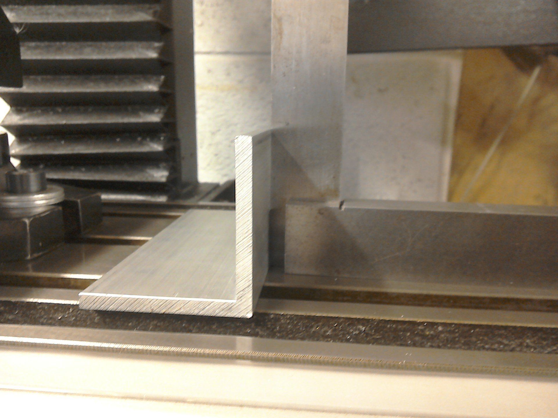
If you're using angle like this, you may well find that it isn't exactly 90 degrees (notice the gap between the top of the aluminium angle and engineer's square). Some suitably applied pressure with the hydraulic press soon sorted it out.
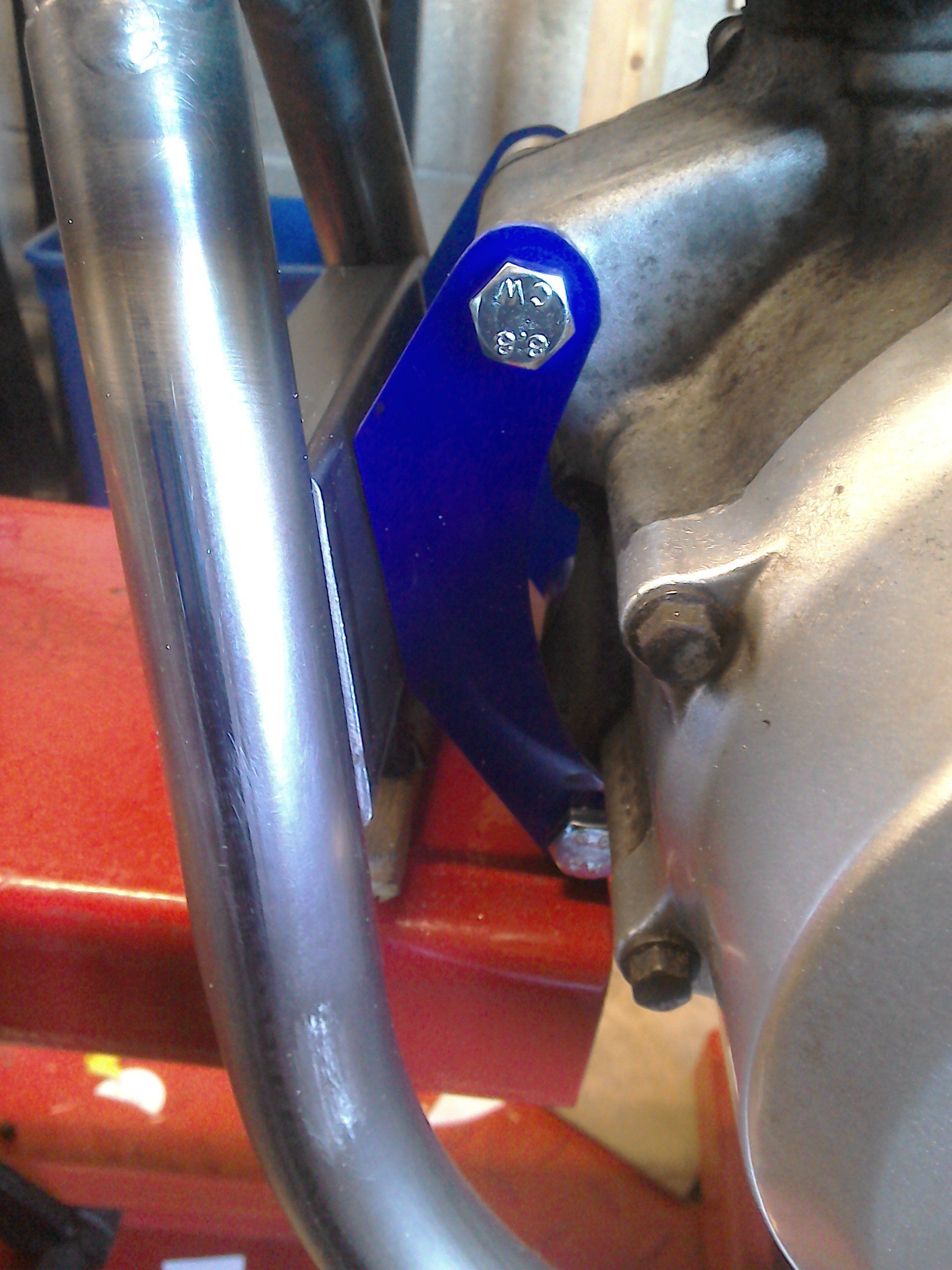
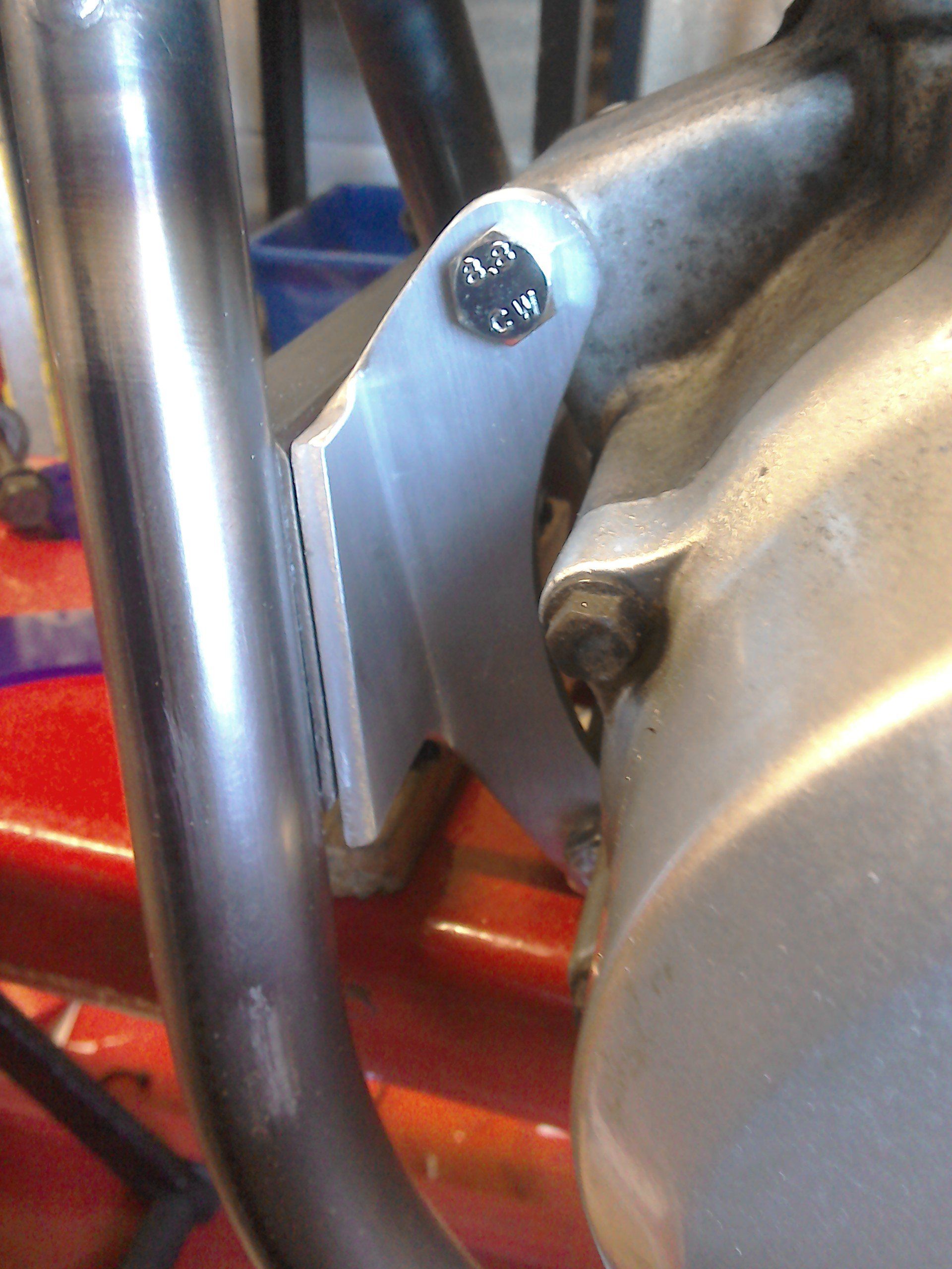
The pictures below show some blue plastic used to make a template for the engine mount, before it was replicated in aluminium.
But, while my physical presence has been required at various Christmas gatherings, my mind has been elsewhere… mostly thinking about the rear engine mounts, and I think a plan may be emerging.
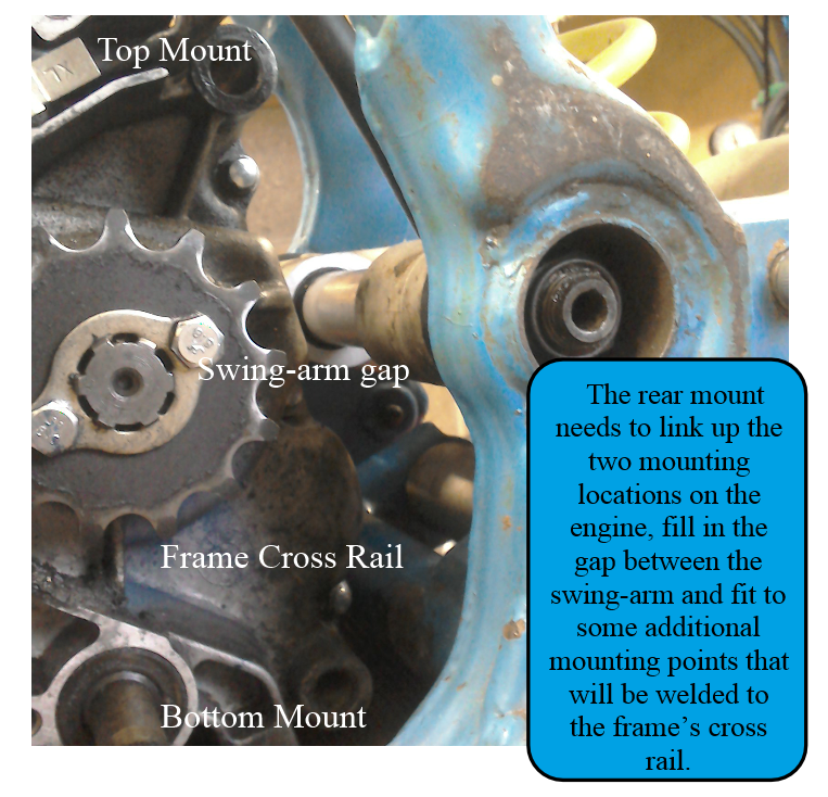
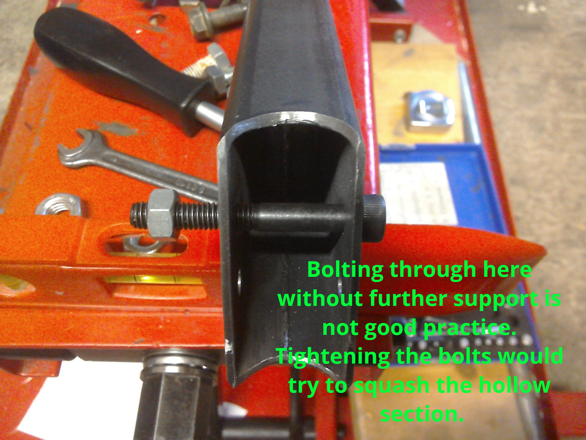
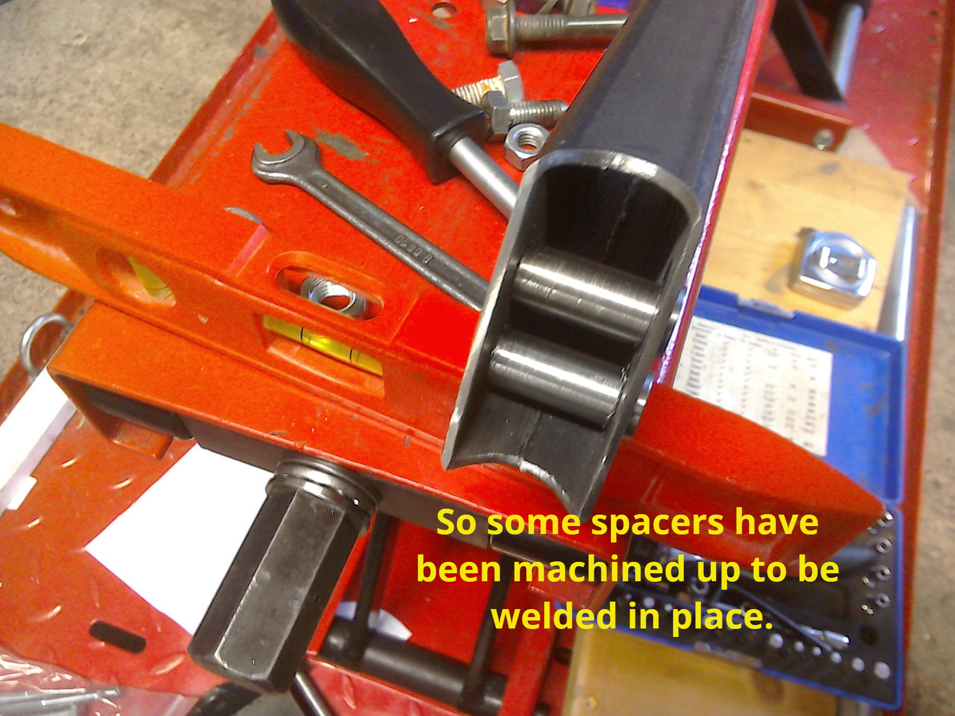
As with the front mounts, the rear mounts must bolt in place after the engine is in the frame. The rear of the crankcases of the original engine were designed to allow the swing-arm to sit either side of it, with the swing-arm bolt passing right through. This formed the rear engine mount. The new engine is not so designed, so currently there is a gap (filled with a spacer at the moment). The plan, then, is to weld some mounting points on the frame’s bottom cross rail, and then fabricate a structure that mounts to these, the swing-arm bolt and the two engine mounts.
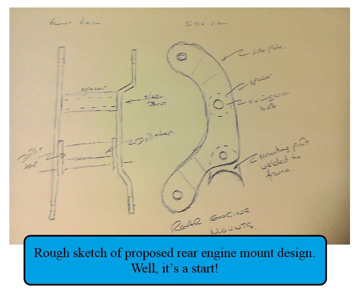
Hopefully, something like the sketch on the below…
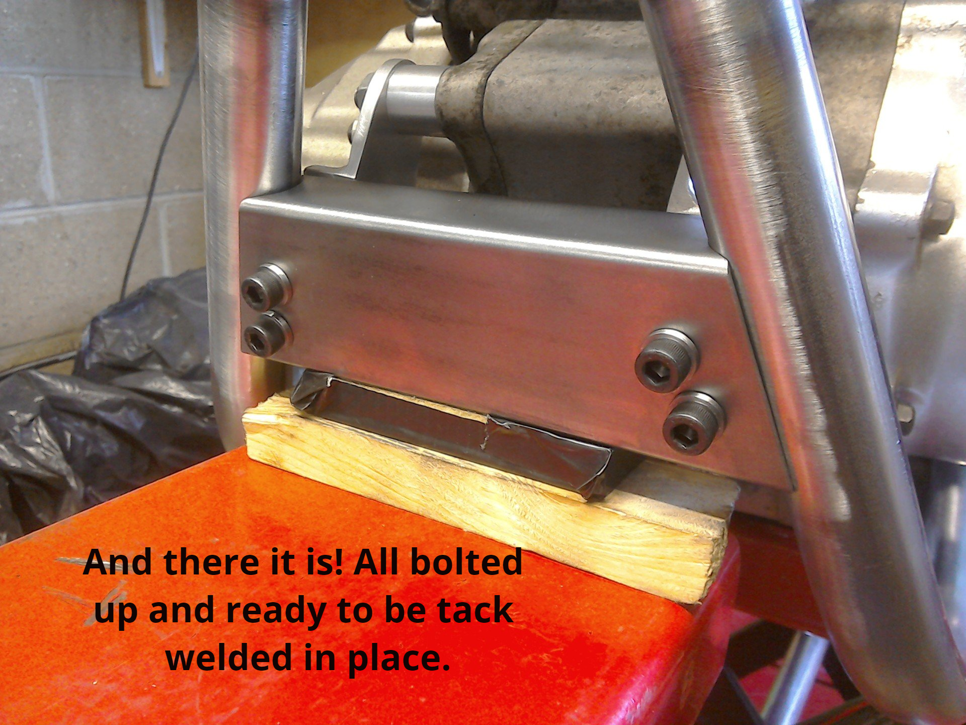
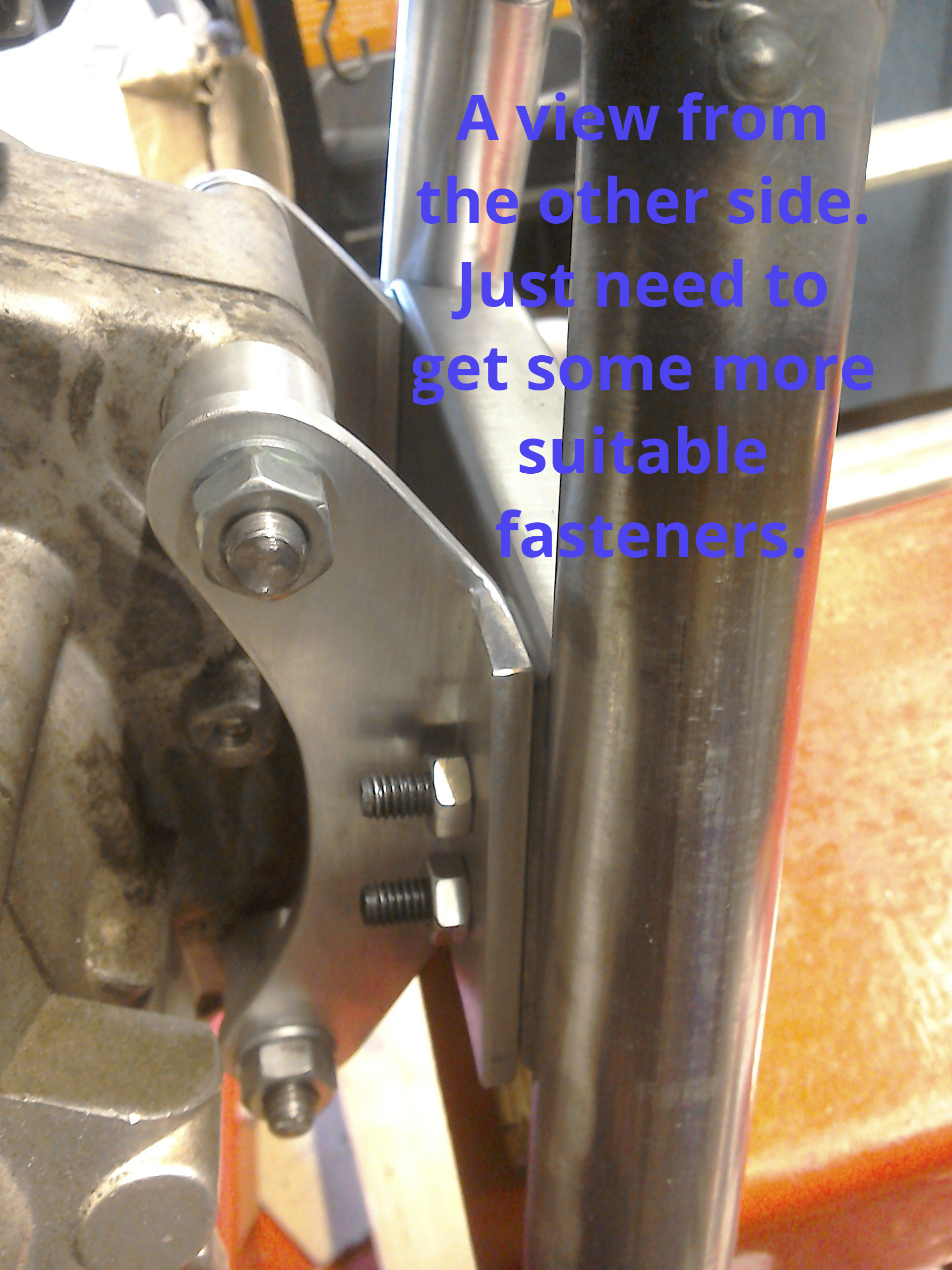
Progress! The front engine mount is complete. It just requires tack welding in place and the sourcing of some more appropriate fasteners.
Here's a pictorial run through of making the brackets.
Here's a pictorial run through of making the brackets.
Now it's time to make a proper start on the rear mounts. Could be tricky...
Flushed with success at having finished the fabrication of the front mounts, and having tack welded them in place, I turned my attention to the rear mounts.
To get a better view of the job, I decided to remove the rear wheel. And that’s when my heart missed a beat.
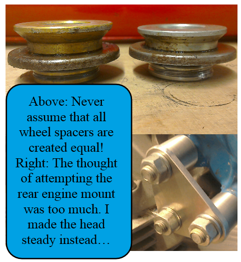
Overlooked by me when I slung the wheel in, but blindingly obvious now I came to take it out is the fact that the wheel spacers are of different lengths. Had I struck lucky when I put the wheel in and got them the right way around? Or had I just lined my engine up to a rear sprocket that itself wasn’t in the right place?Time to refer to the manual.
Thankfully, despite my inability to correctly pick the winning lottery numbers, it seems I did manage to correctly (unwittingly) pick the right spacer orientation, and so all is still Ok.
After all that excitement, I took one look at the rear mounts, fried my brain, and decided to start with something easier and make the head steady instead! More pictures of that follow below...
Time to turn these pieces of aluminium into the engine head steady (and replace the temporary plywood one with something more permanent).
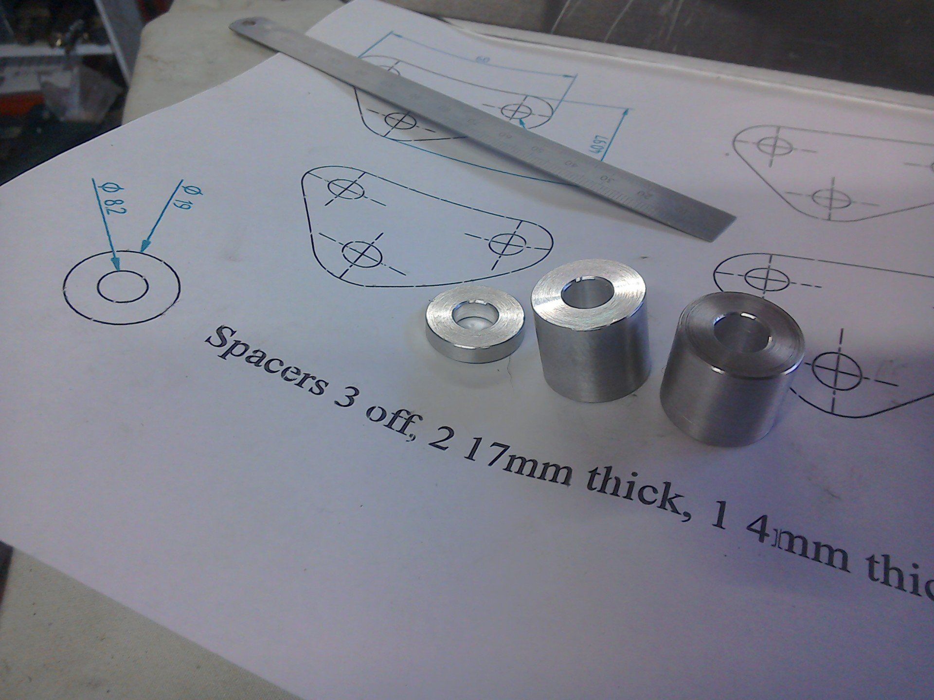
That's the spacers done.
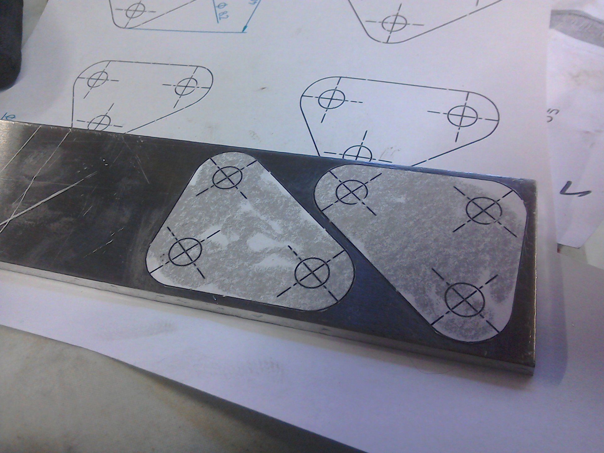
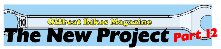
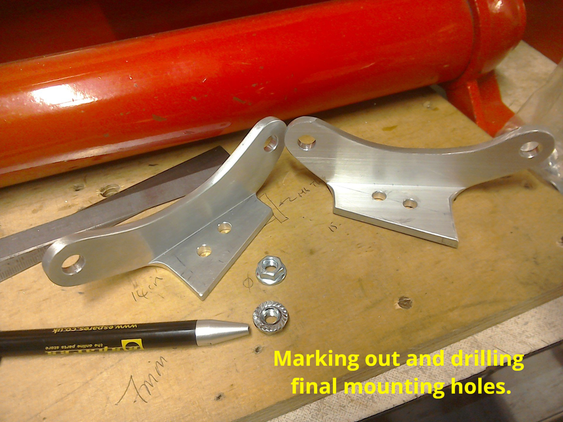
I cheat when marking out pieces like these. After drawing them in CAD, I print them out full size and stick them to the aluminium. Usually I use a glue stick (Pritt) which makes them easy to remove, but I didn't have any, so used superglue instead. This made sure that they didn't move while I was working on them, but it was much harder to remove the paper after I'd finished.
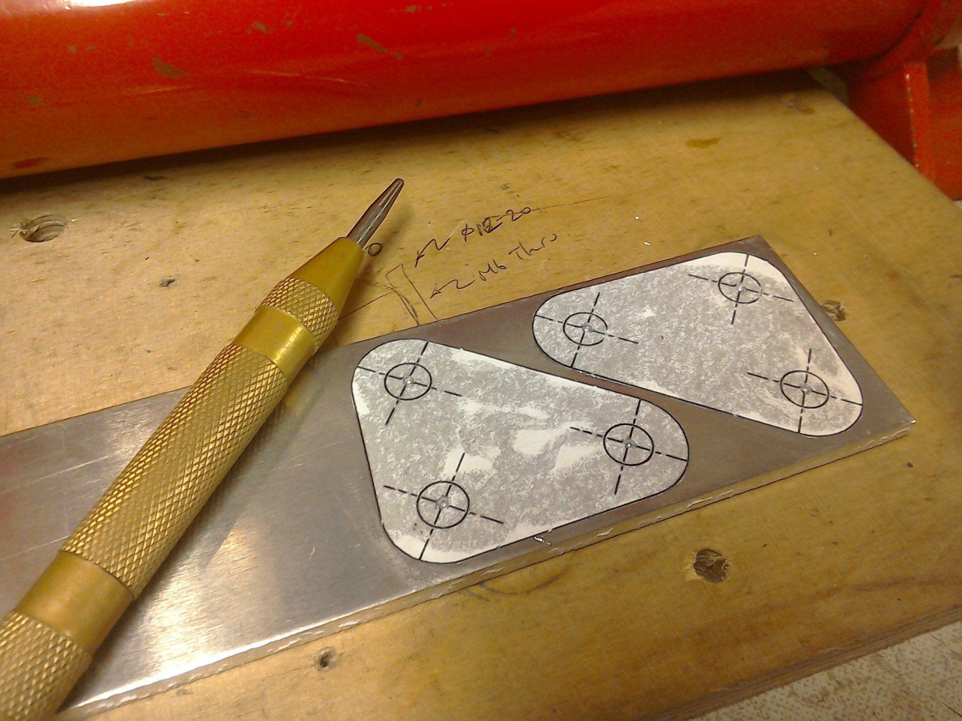
Hole positions are then centre punched...
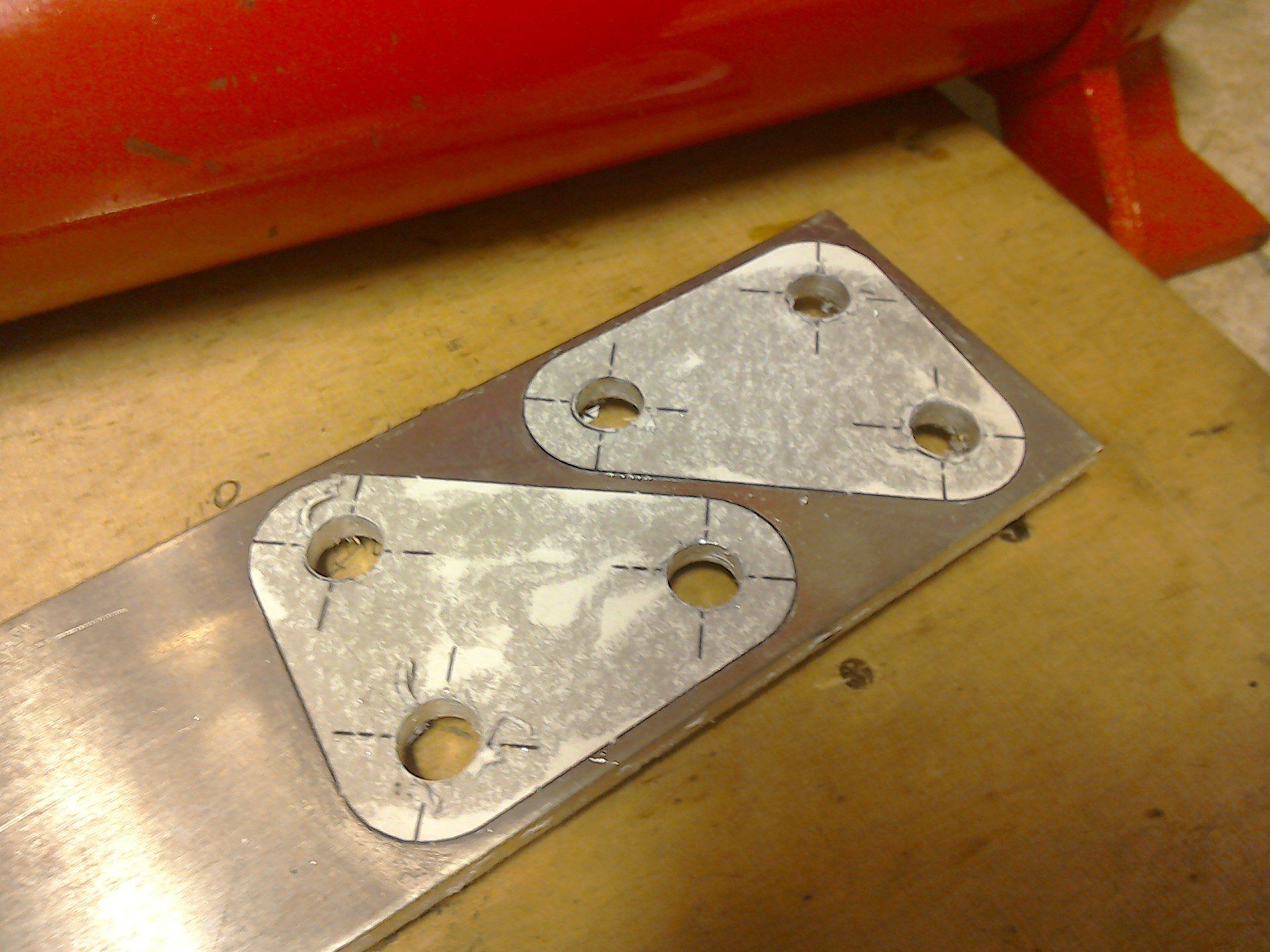
... before being centre drilled and then drilled to final size.
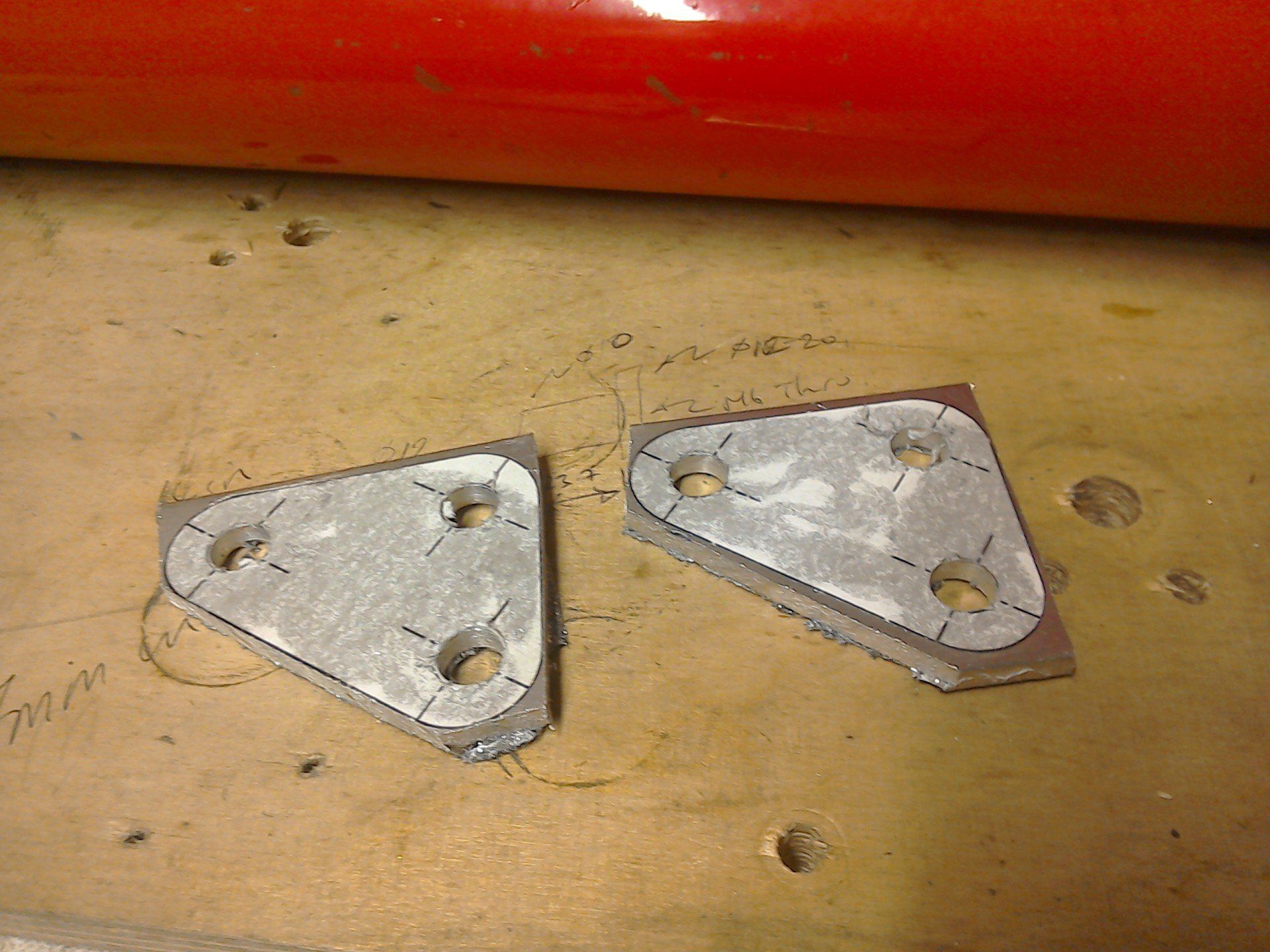
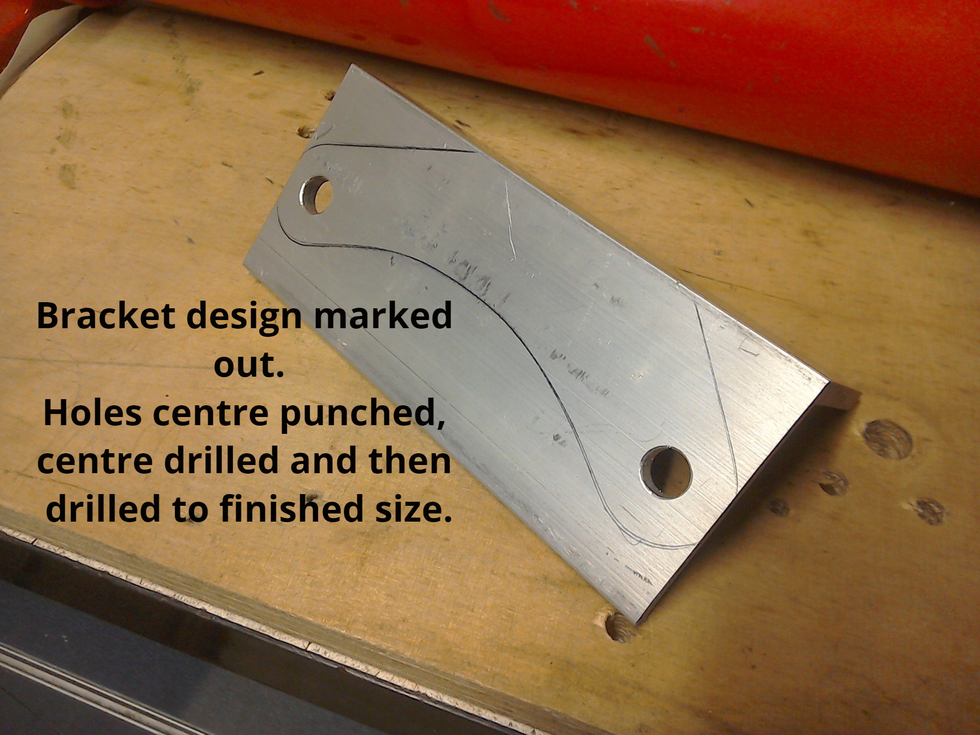
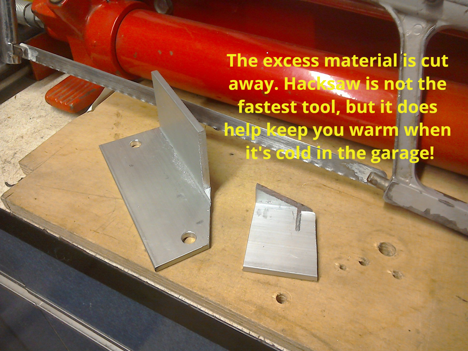
Brackets are then cut roughly to size using the trusty hacksaw.
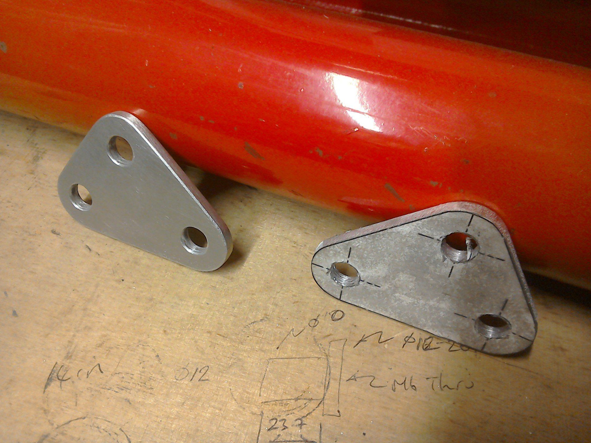
Before being finished to size using angle grinder, files and emery cloth. Left one is finished. Right one requires a bit more final finish work and the removal of the paper template.
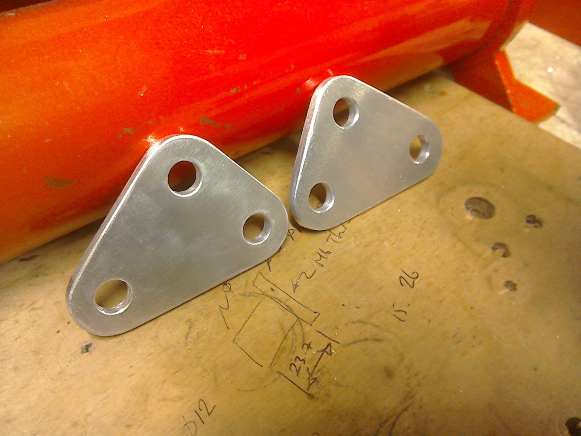
Both sides now finished and ready to bolt on.
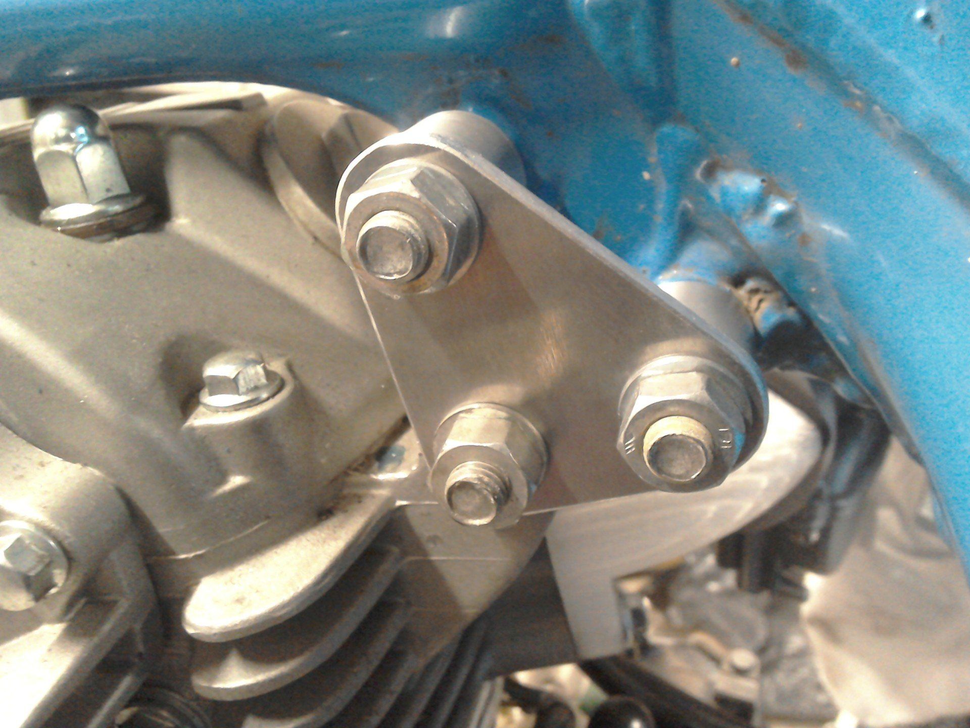
Finished brackets and spacers bolted in place.
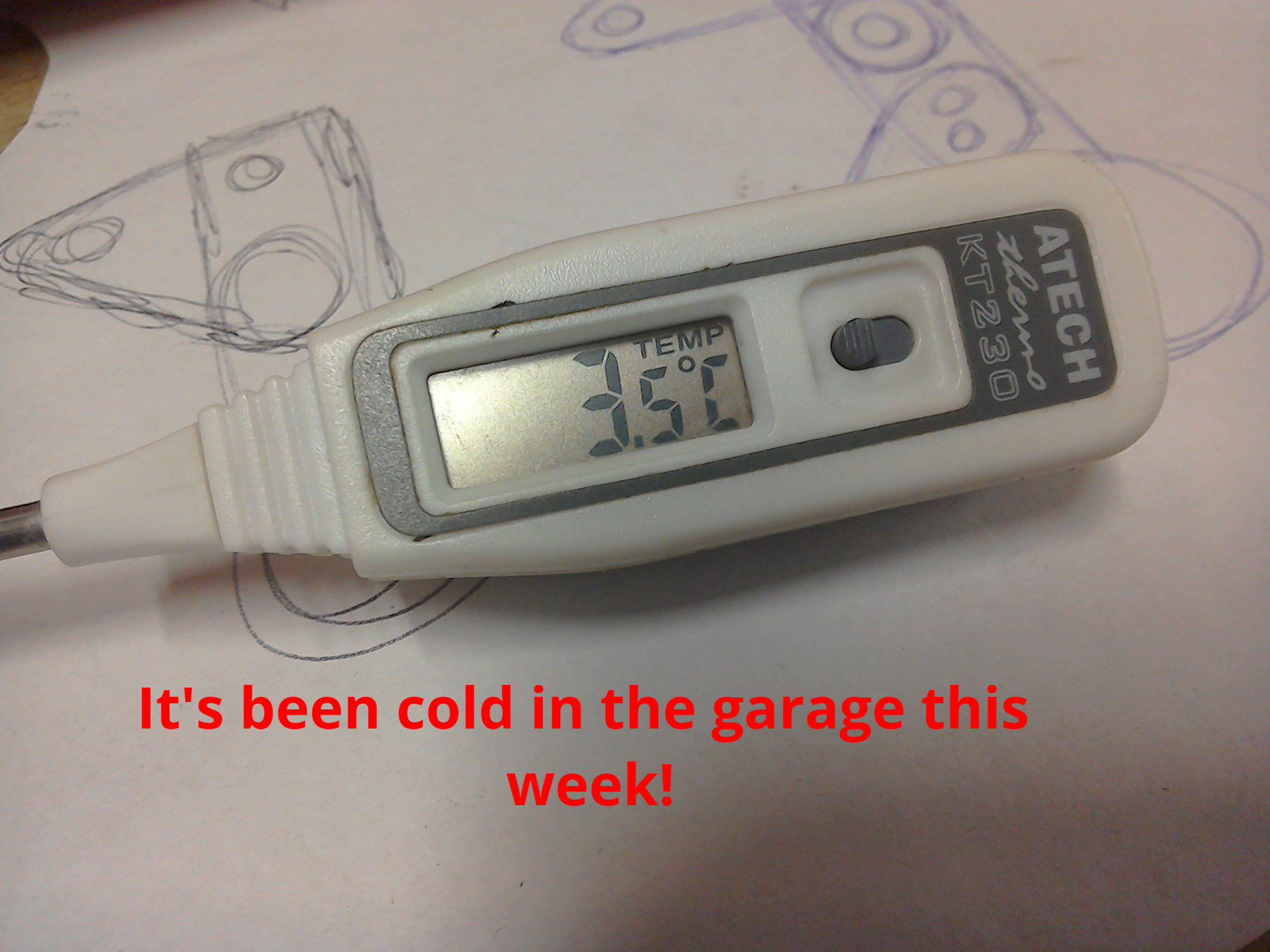
So, I’ve bitten the bullet, braved the cold of the garage and made a start on the rear engine mount.
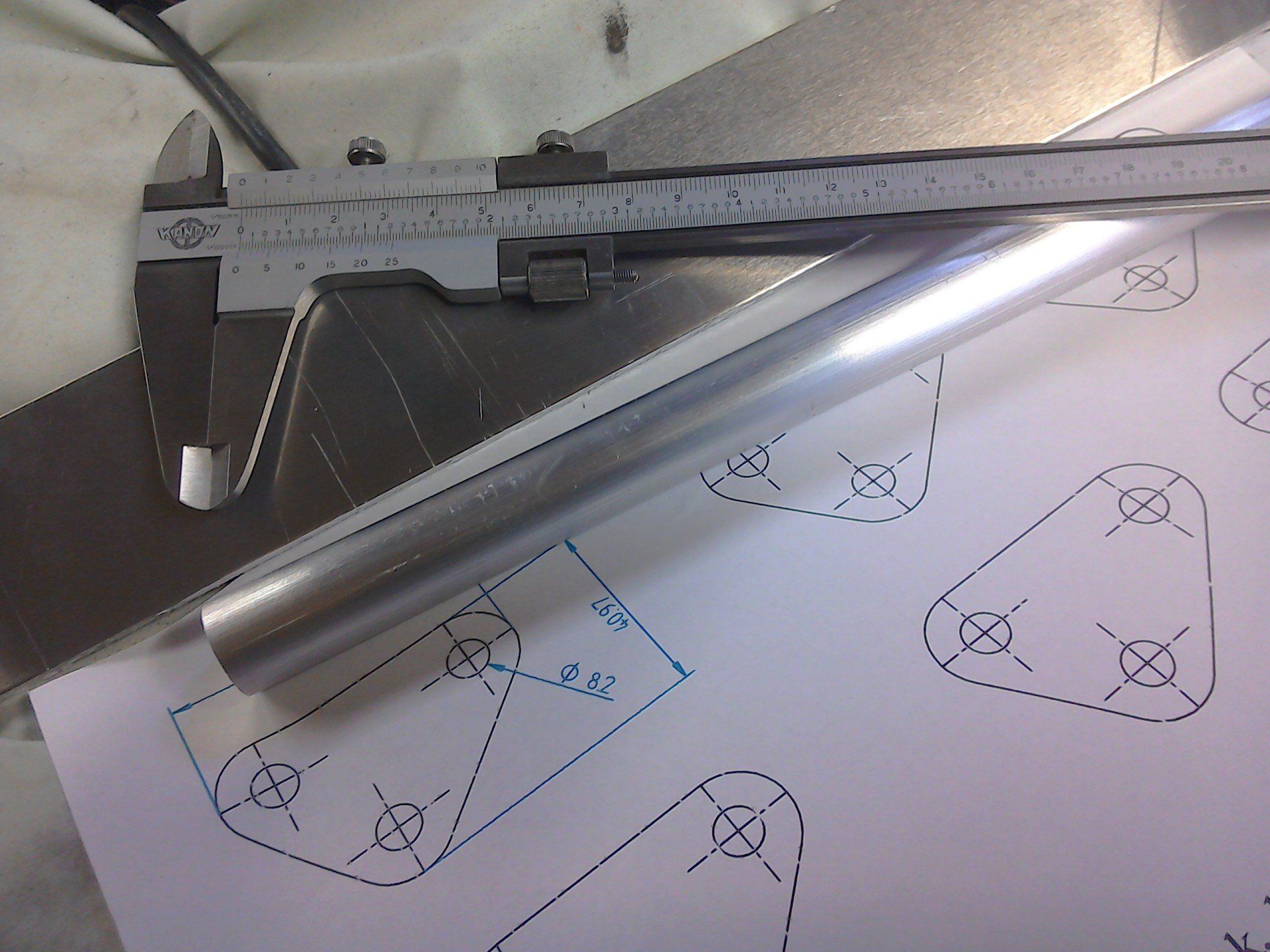
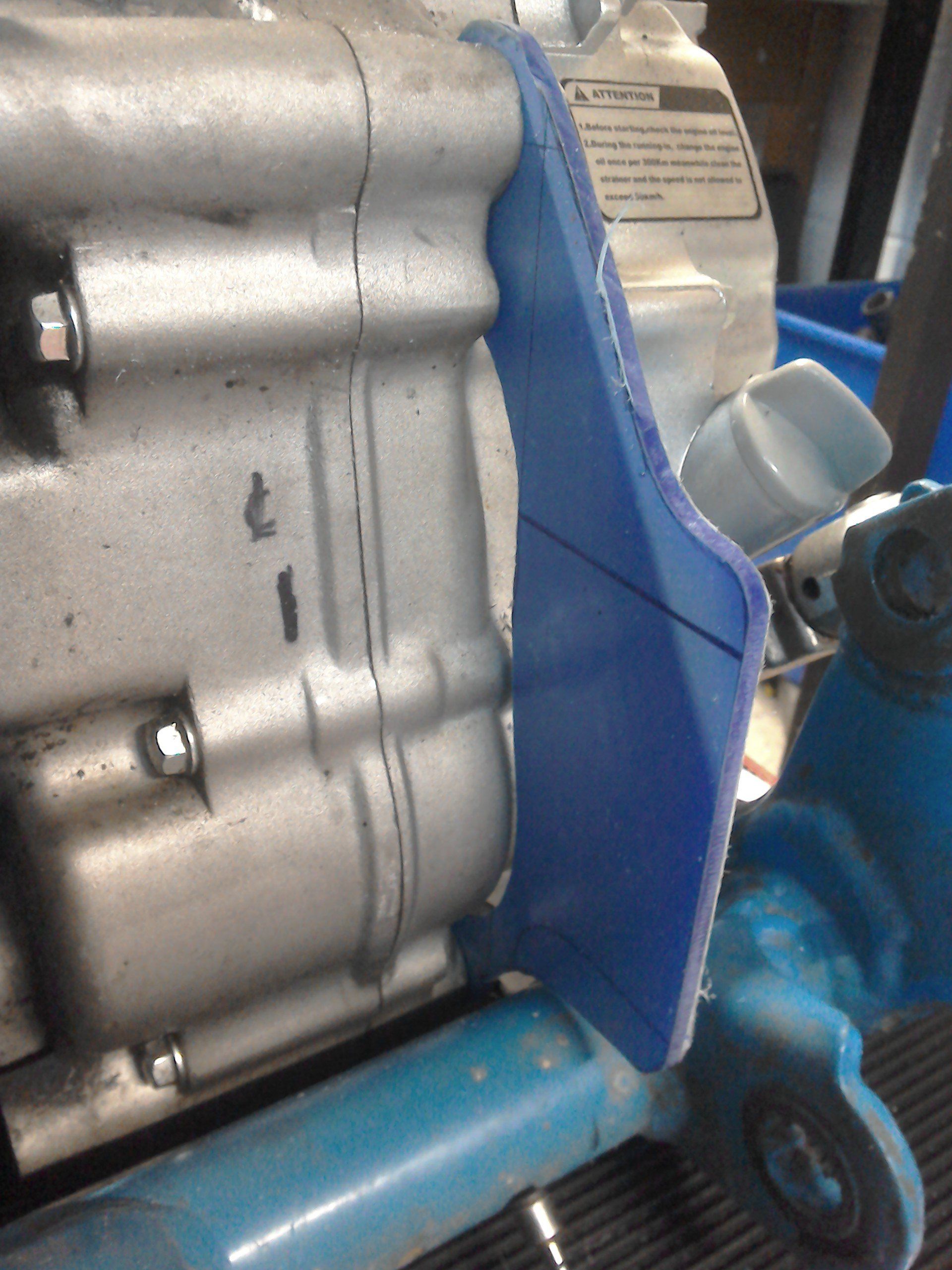
First job is to measure the distance between the mounting holes on the engine and the relationship of these to the swingarm pivot position.
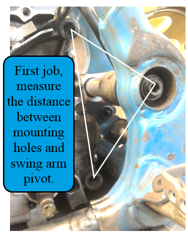
Not an easy job to do, it’s difficult to get access with conventional measuring tools. So I used a low tech alternative; a piece of paper and a greasy finger, followed by some engineer’s marking blue. The paper was cut to fit around engine and swingarm, and then held in place whilst the greasy finger was used to mark the hole positions. The paper template can them be used to get a good idea of the distance between the hole centres.
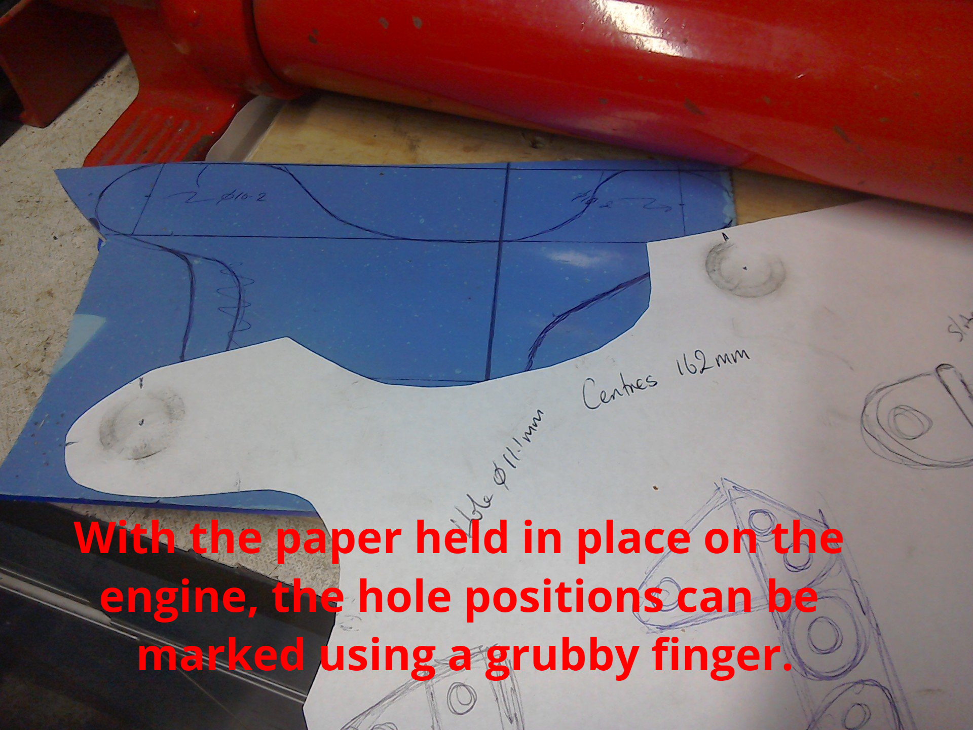
This paper template was then used to make a more rigid plastic version.
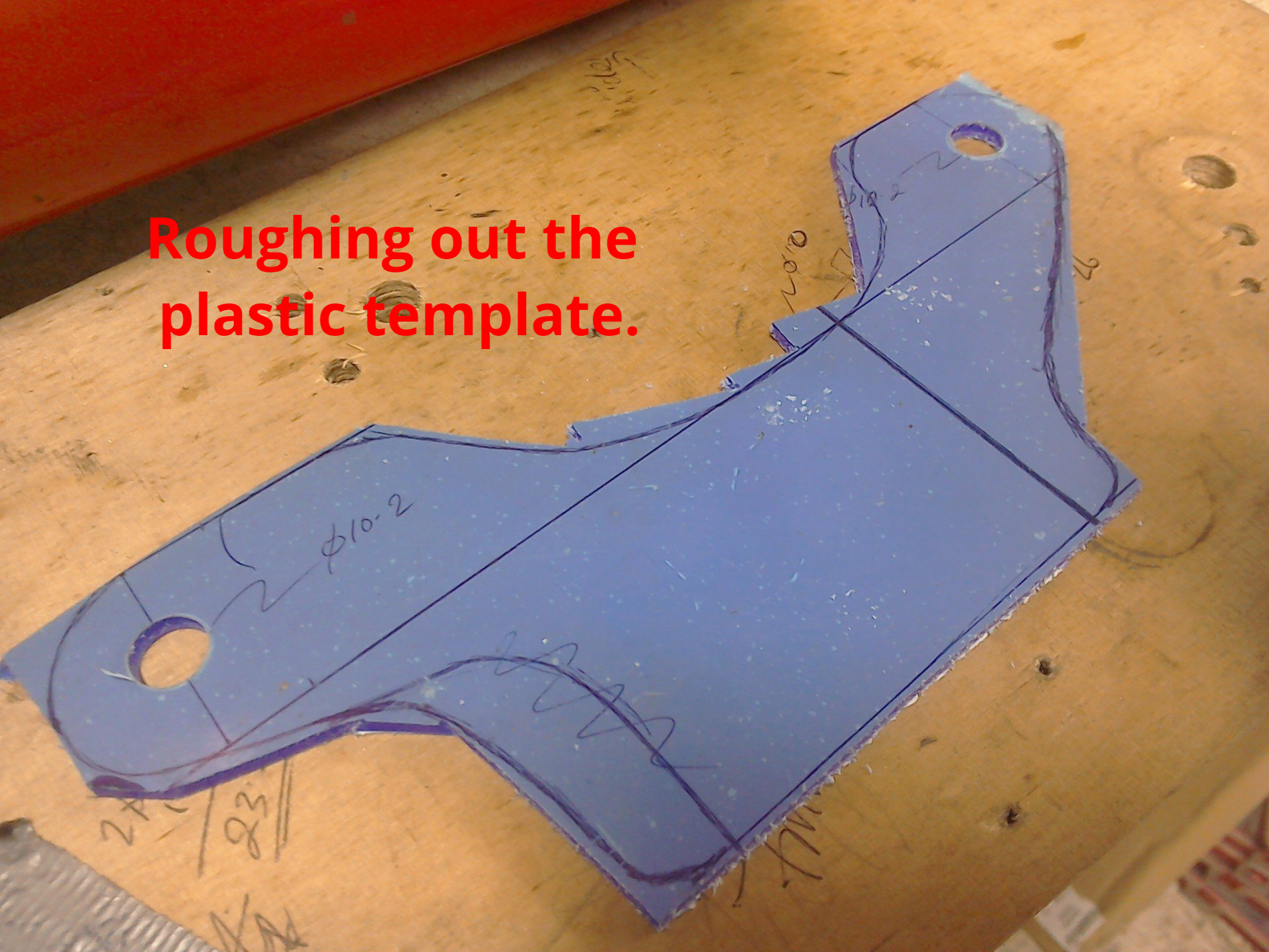
And after some work with the angle grinder and files, a nice fitting template was produced.
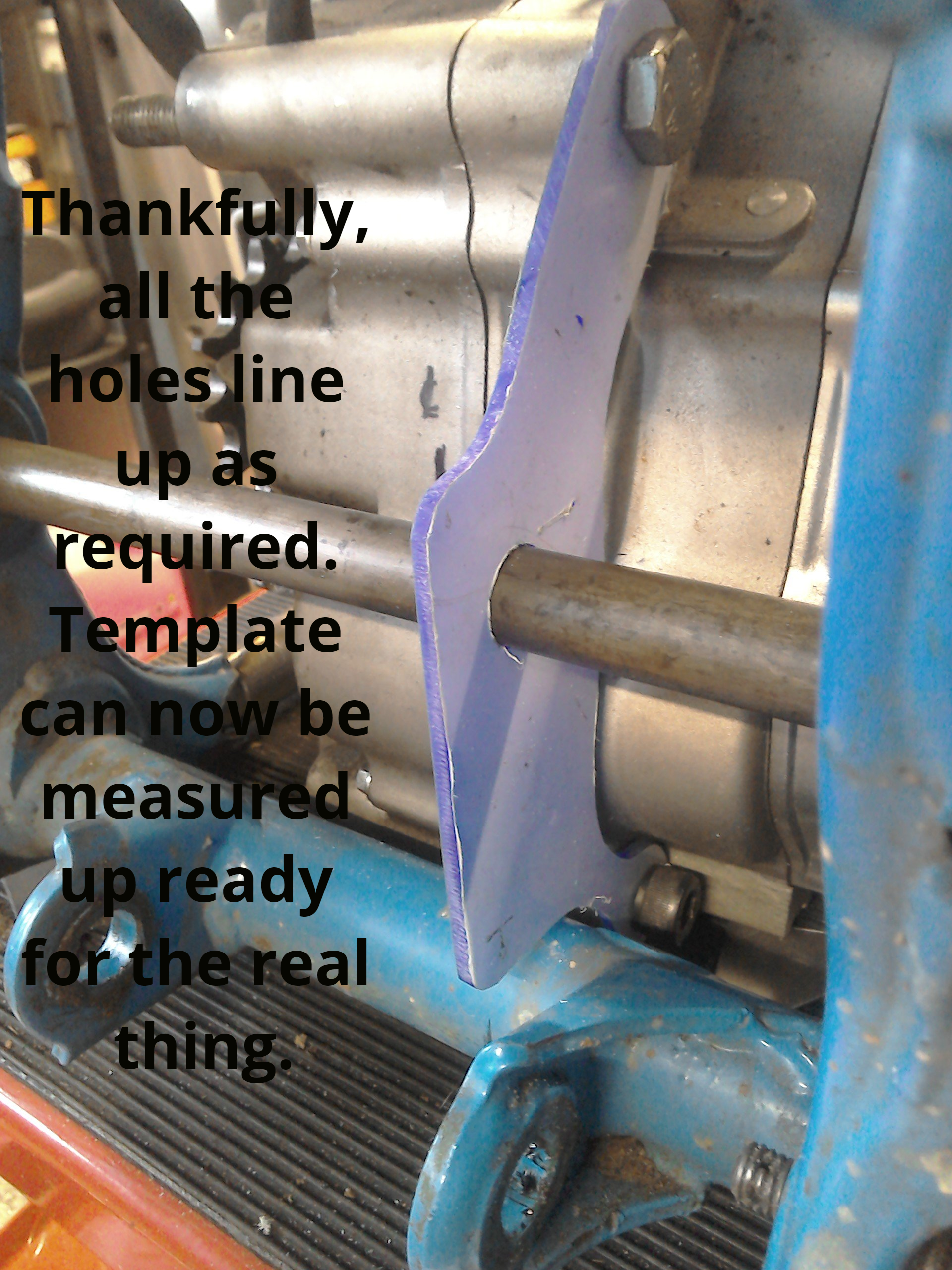
By smearing engineer's blue on the swingarm bolt, and carefully inserting it through the frame (making sure that it's straight and level) the hole position for the swingarm bolt can be transferred to the template.
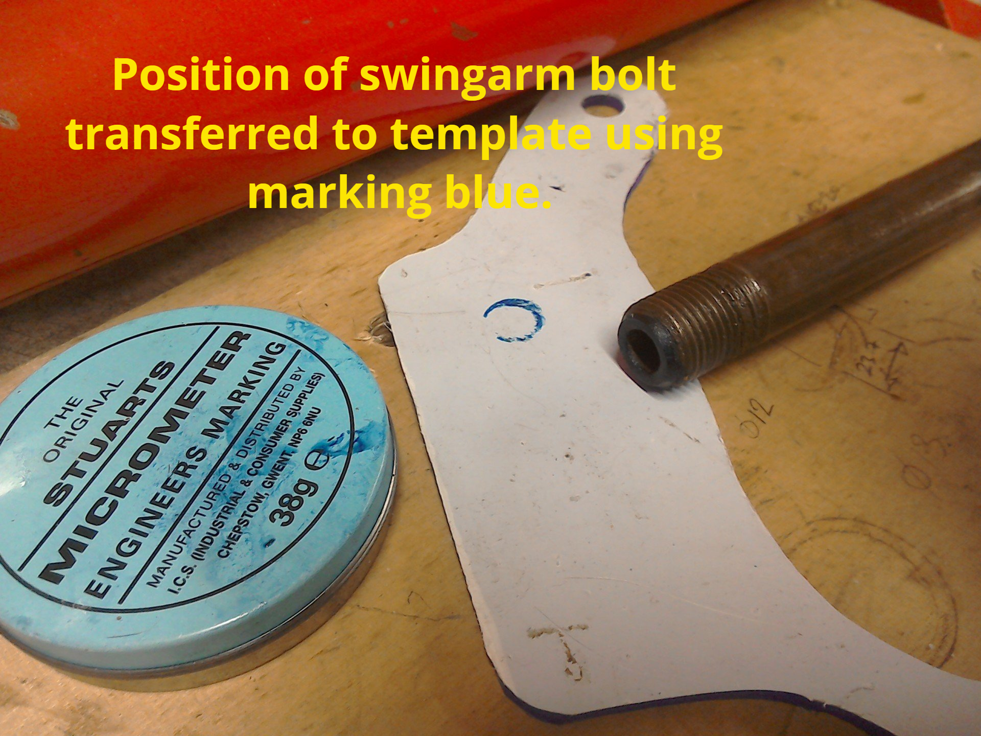
The hole for the swingarm bolt can be drilled, and the template put back on the bike. Hopefully, all the bolts will fit through the required holes and the template can be measured up. Now I've got a better idea of the relationship between engine mounting holes and swingarm pivot, all I have to do is come up with a design to link them all together...