December 2018
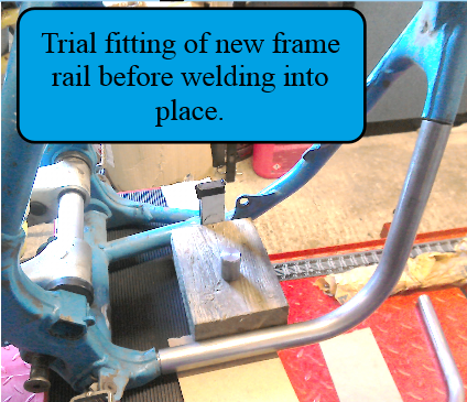
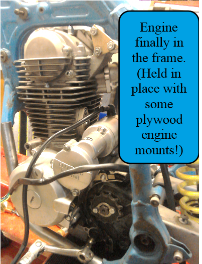
One old frame rail is now out and the new one welded in place. This then allowed me to remove the second original frame rail and (at last) lift the engine in place, to see if it really will fit.
After a lot of adjusting to get the front and rear sprockets aligned, and with the help of a scissor lift and some temporary plywood engine mounts, the engine is in place. I now have to decide if the second frame rail needs to be removable in order to be able to get the engine in / out. That, in turn, will depend on the engine mounting points chosen, so I need to think about those too!
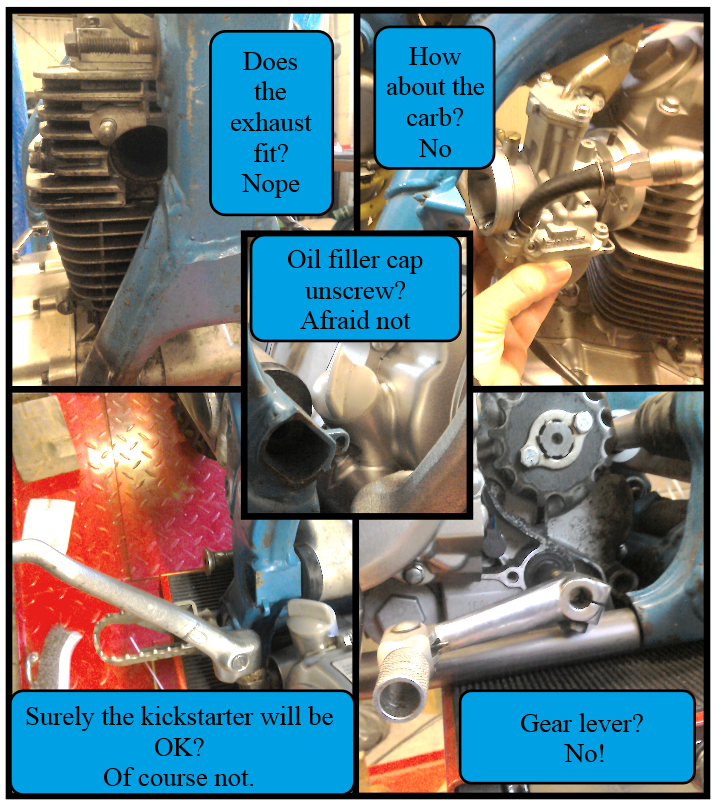
While I was at it, I thought I’d check the fit of some of the ancillary equipment: exhaust, carburettor etc. Guess what, they’ll all just bolt on! Just kidding. The exhaust fouls the front down tube. There isn’t enough room for the current carburettor. The kickstart lever will hit the footpeg. The gear lever bolt will be inaccessible once the engine is in the frame and you can’t unscrew the oil filler cap. So, lots more stuff to think about, then. But it’s all part of the fun, isn’t it?
Time, then, to address some of the issues uncovered during the trial fitting of the engine:-
An exhaust pipe cannot be made to fit without some modification of the frame’s existing down tube. Using the tightest, suitable exhaust bend that I can find (see pic below), it should be possible to do this with a slight ‘shaving’ of the down tube. The existing design is pretty chunky, so with care, it’s possible to do this and (hopefully) minimise impact on the structural integrity of the frame.
An exhaust pipe cannot be made to fit without some modification of the frame’s existing down tube. Using the tightest, suitable exhaust bend that I can find (see pic below), it should be possible to do this with a slight ‘shaving’ of the down tube. The existing design is pretty chunky, so with care, it’s possible to do this and (hopefully) minimise impact on the structural integrity of the frame.

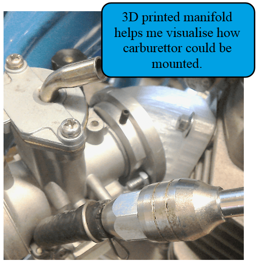
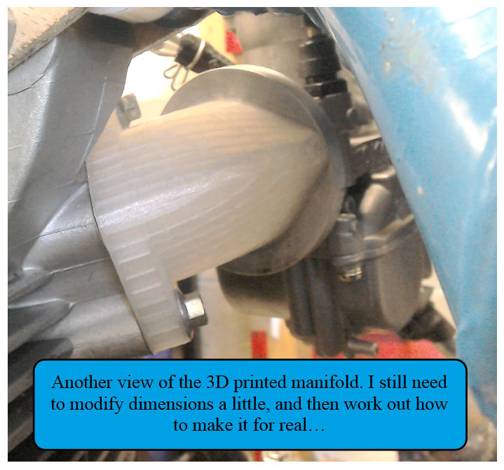
The carb is slightly trickier proposition and will need a custom built manifold to position it at almost 90 degrees to the engine. (Which is the only space in which it will fit.) Using the 3D printer, I’ve managed to get close to the size and shape of manifold that it will require. All that remains now, is to work out how I’m going to fabricate it in something more durable than the plastic used by the printer!
I’ve still got to work out air filter / airbox arrangements. I've purchased the filter shown below, but mostly because I just want to make use of the 90 degree, rubber fitting. I would prefer some kind of airbox, rather than to use an individual, pod type filter.


The kickstart lever isn’t too much of a problem as the engine also has electric start. So, I’ll leave this for the moment, although I would like to have it as a backup. I don’t think finding or modifying a gear lever to fit the available space will be too much trouble. And finally, the oil filler cap. Well, I’m still thinking about that…
For now, I’m going to concentrate on the engine mounts. Designed to be multi-use, the engine has five possible mounting points. It’s a case of deciding how many and in what configuration will provide the best mounting for this application…
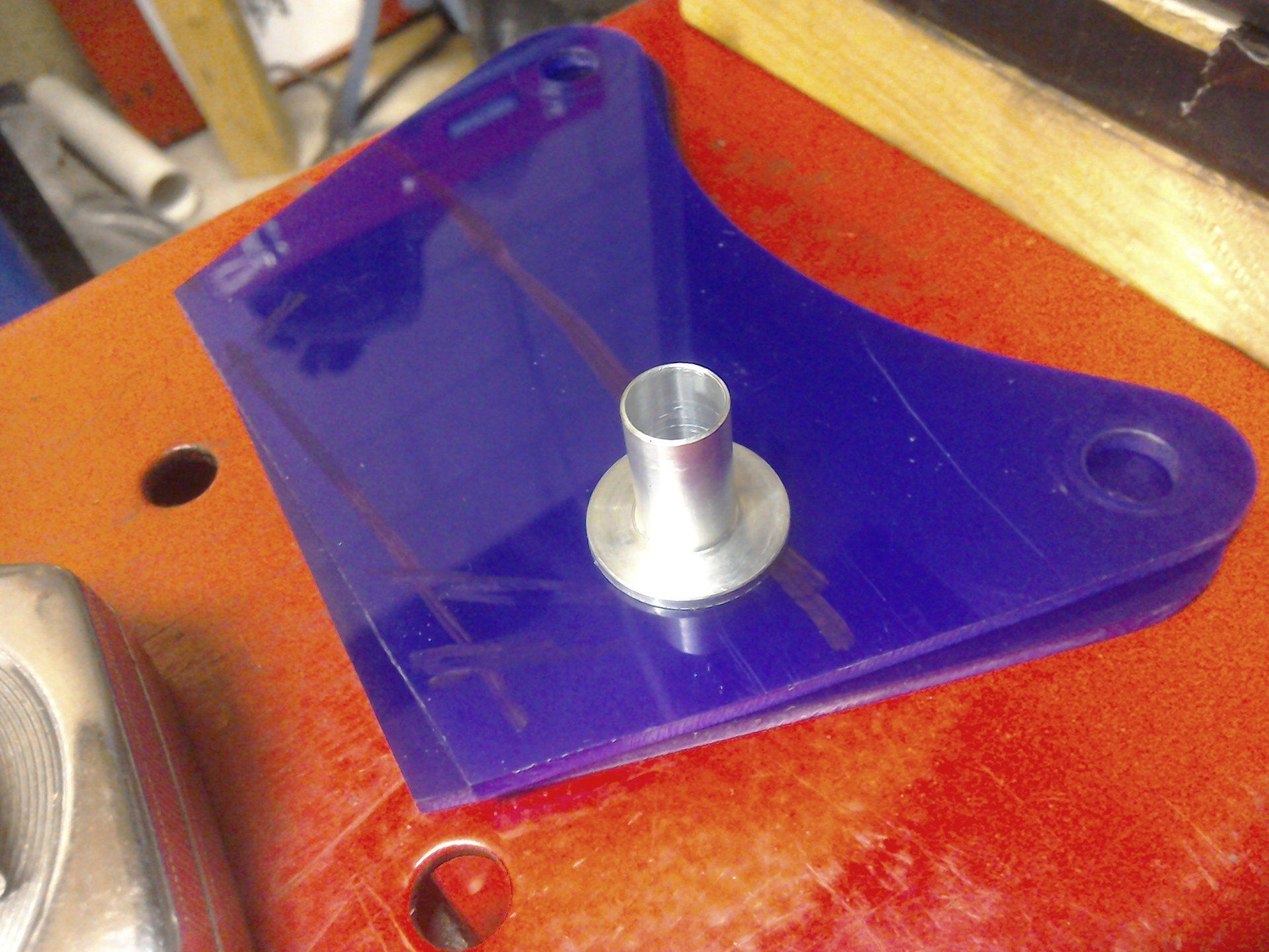
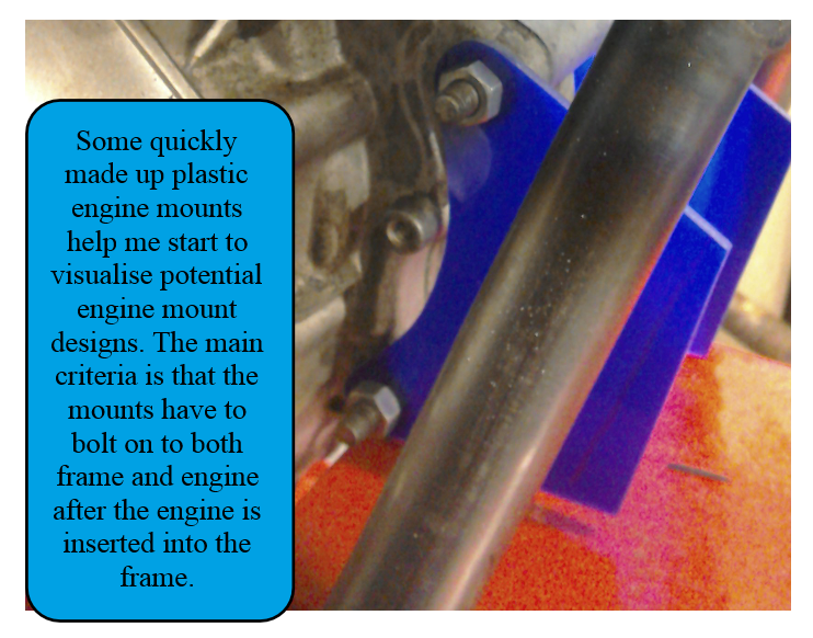
Engine mount time, starting with the front mount. Usually, I like to sketch potential ideas down on paper first, but sometimes (like this time) I don’t have any ideas! So, in these cases I just have to go and try something, anything, eye it up and hope that it triggers some inspiration. Here, I started by making some simple flat mounting plates out of some 3mm plastic that had been lying around in the garage for years. It’s easy and quick to cut, shape and drill holes in, so is perfect for just trying stuff out.
Then I stood and looked at them for some time…
Eventually I sketched out this…
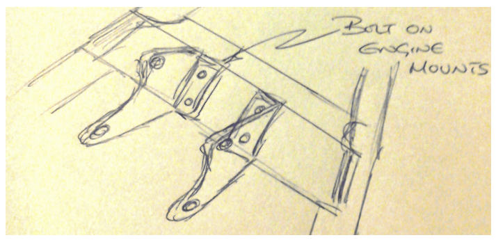
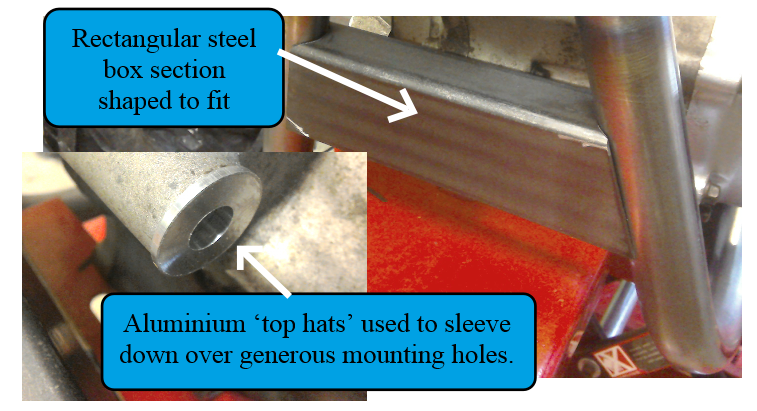
And that’s the kind of thing that I’m now going to try and implement. A suitable length of rectangular steel box has been purchased and shaped to fit. (And it's much quicker to write that than it is to do in practice! Much trial fitting, and work with the angle grinder and file was needed before a suitable fit was achieved. All those round tubes and angles make my brain hurt.) Some aluminium ‘top hats’ have also been machined to take up some of the slack in the mounting holes on the crankcase. These were very generously sized for their standard M8 mounting bolts, but not generously sized enough for M10 to be used instead.