
March 2019

More work on the rear engine mounts. Now it's time to start welding all of the bits together. This is the first side being tack welded on the jig...
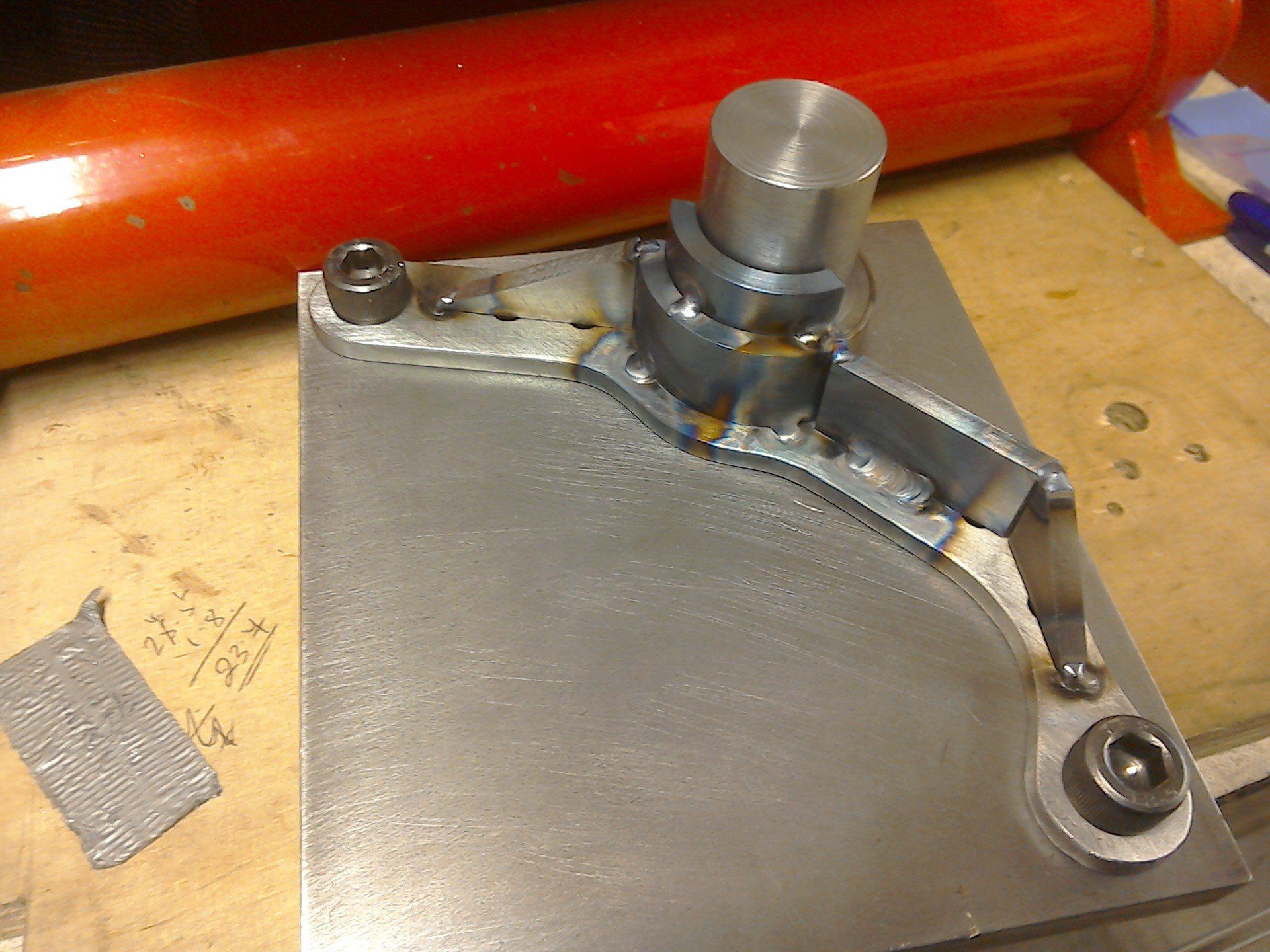
... and then off the jig to access the other side.
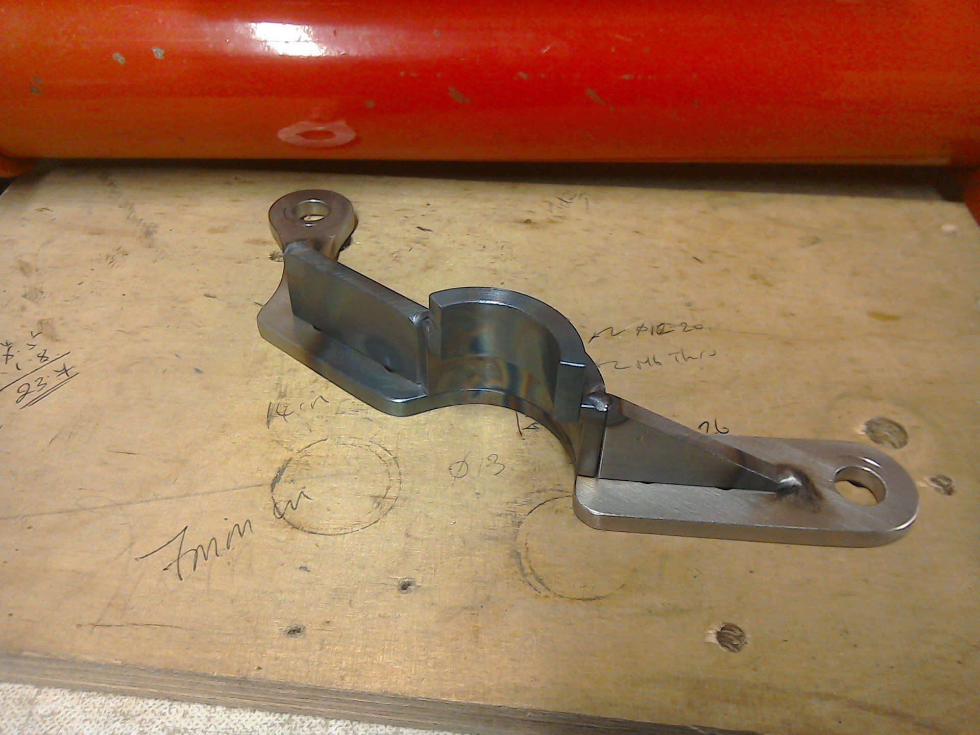
Eventually both sides are fully welded and the spacer has also been fabricated.
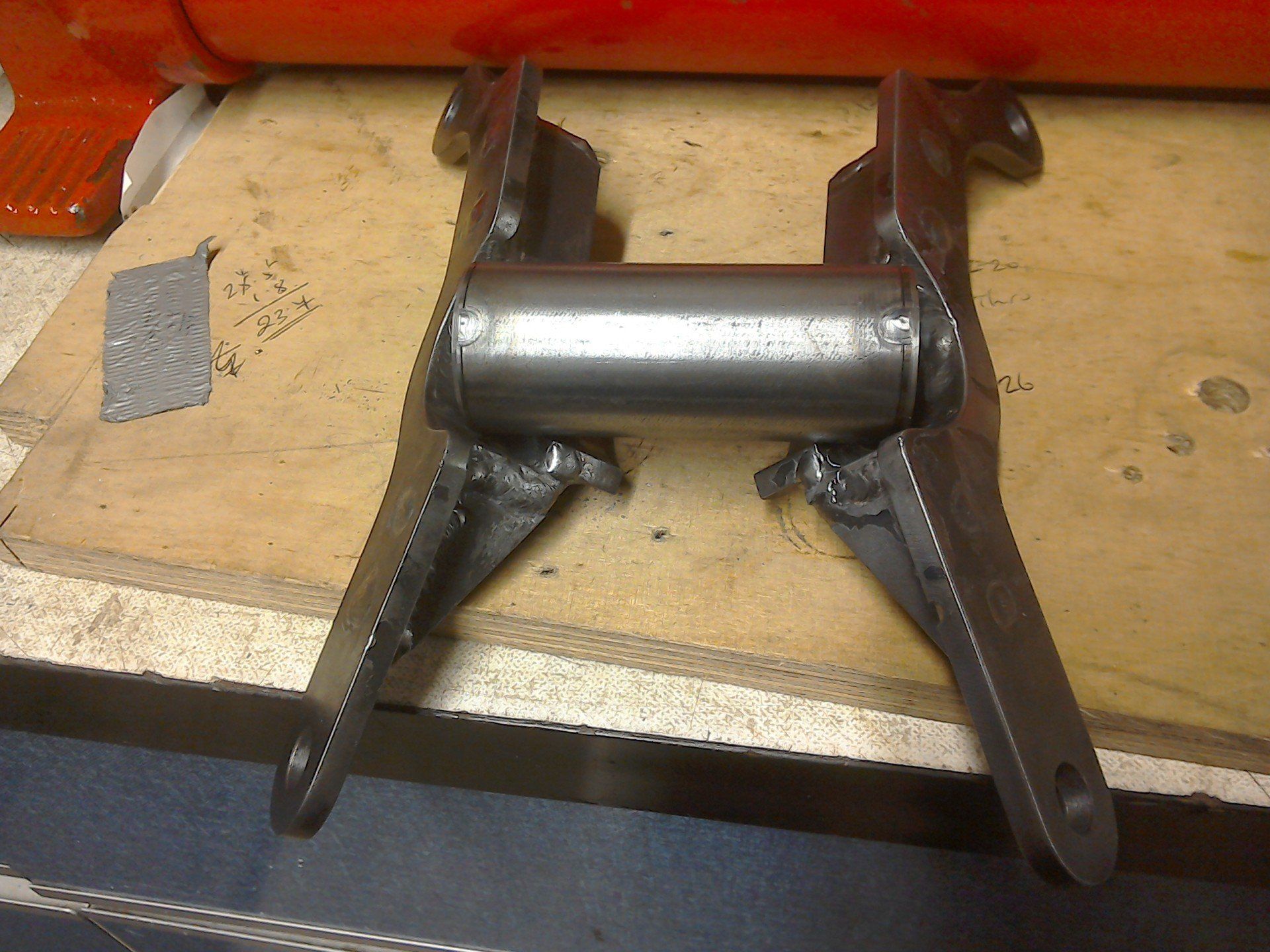
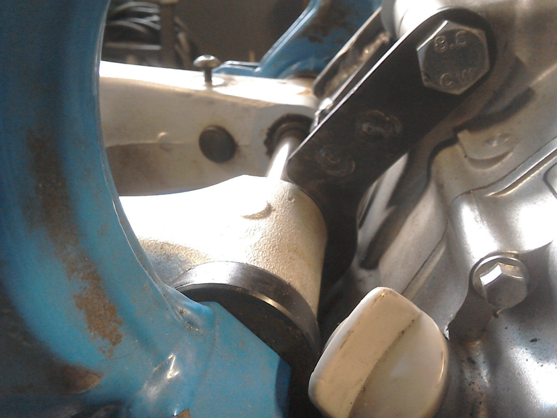
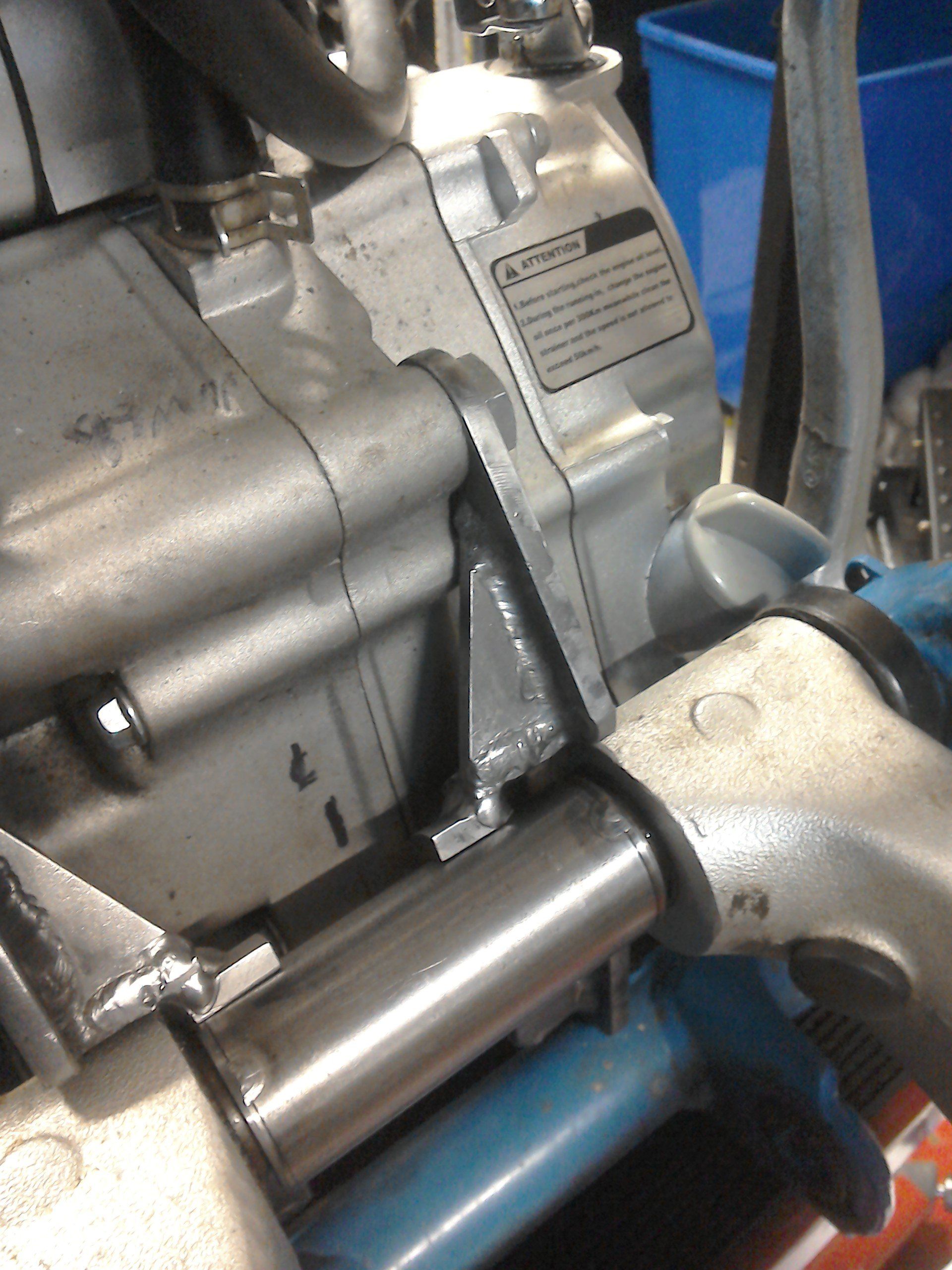
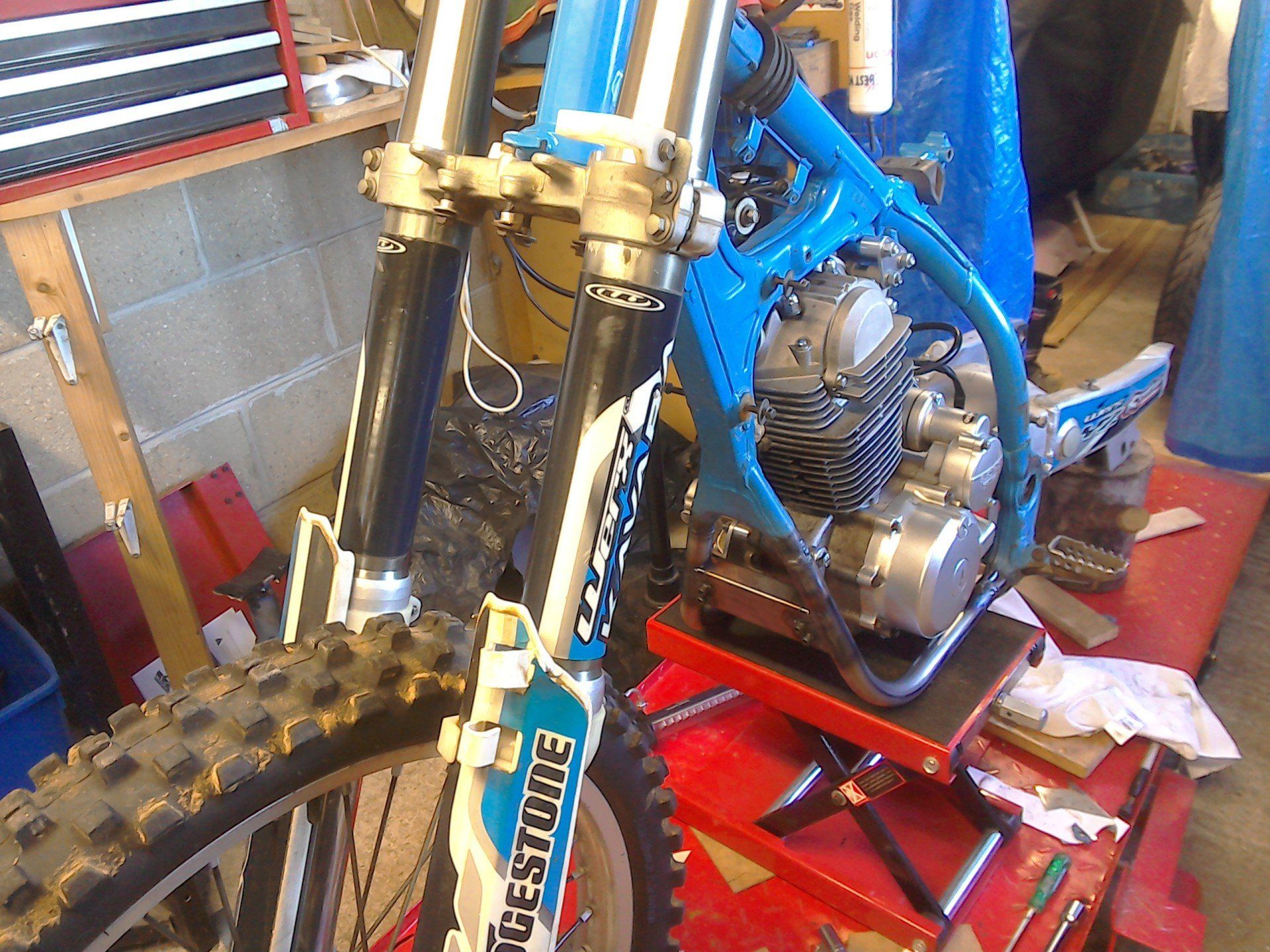
Trial fitting the mounts. This involved removing all of the other engine mounts and twisting the engine to one side in the frame to allow the rear mounts and bolts to be installed, before wiggling the engine back into place. It also showed up a few clearance issues between the mounts and the swingarm (see pic below). To avoid having to move the engine again, I used a die grinder to remove material with the mounts in situ. Eventually, with a little bit of grinding, the swingarm bolt went through, the spacer was seated nicely in the rear mounts and all of the rest of the engine mounts tightened up.
With the spacer now fitting nicely in place, all that remains is for the mounts and spacer to be welded together. Once that's done, engine mounting should be taken care of and I can move on to solving the next problem...
At last, the engine is firmly mounted in the frame.
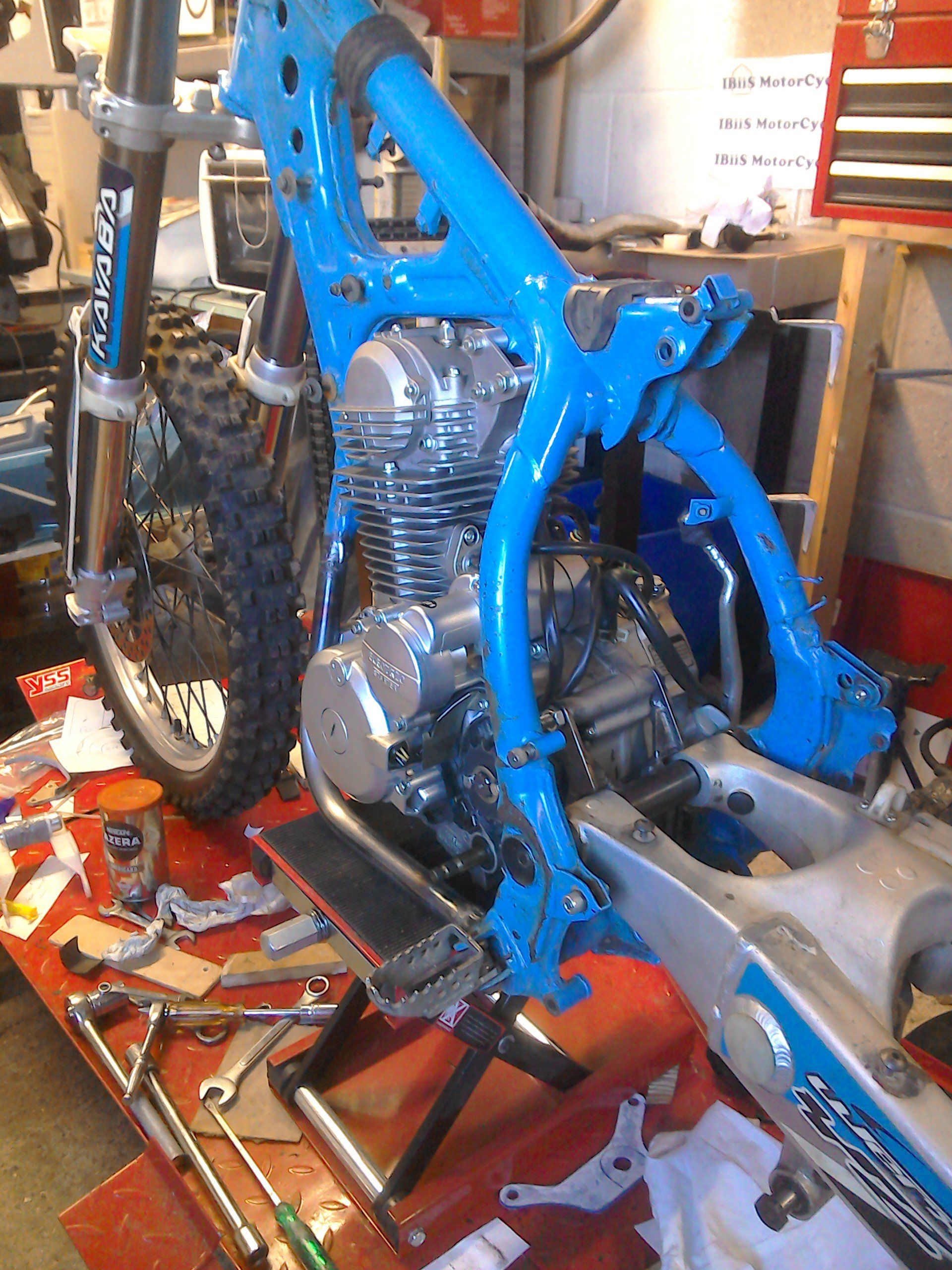
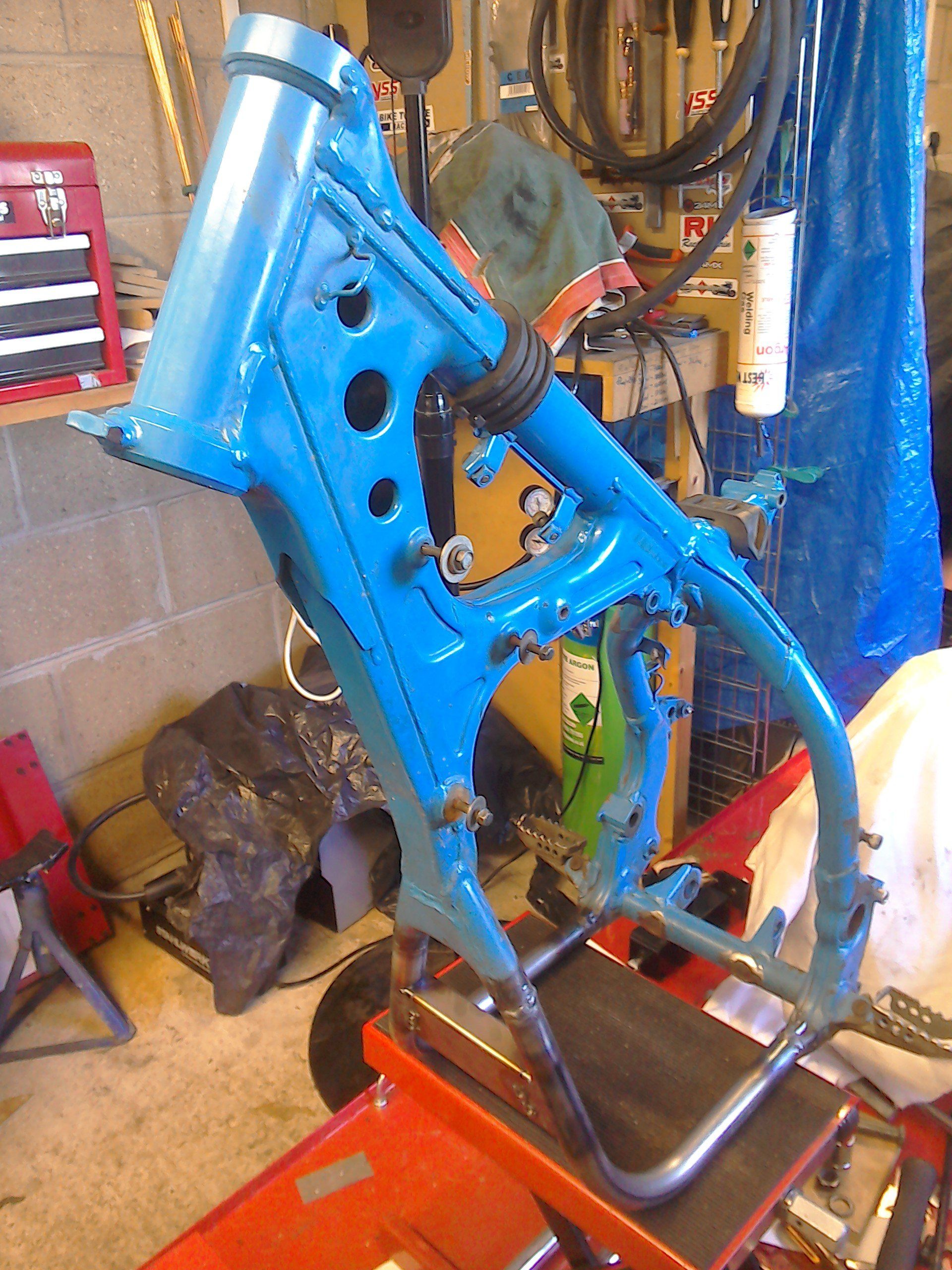
Frame rails and front engine mountings have been fully welded. I would have liked to cross brace the new frame rails as the old ones were (you can see from the rusty circles on the lower cross rail where the original braces were) but the new engine sits down between the rails, so there isn't room. I plan on fitting some kind of sump guard, which (if I design and mount it right) will hopefully both protect the engine and provide some bracing to the frame.
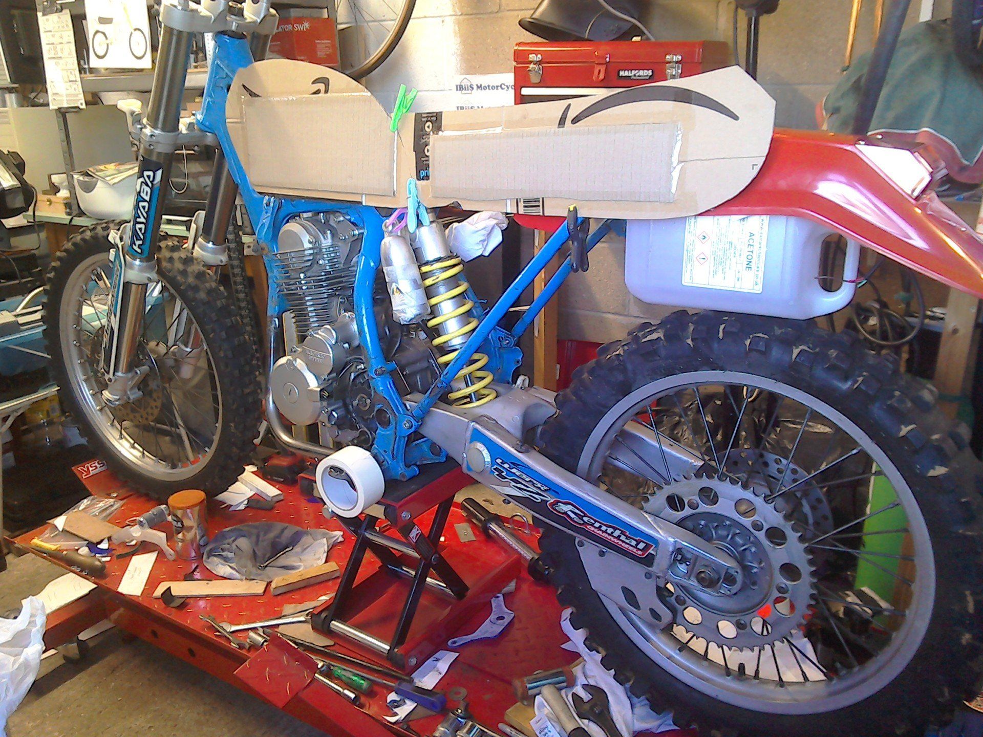
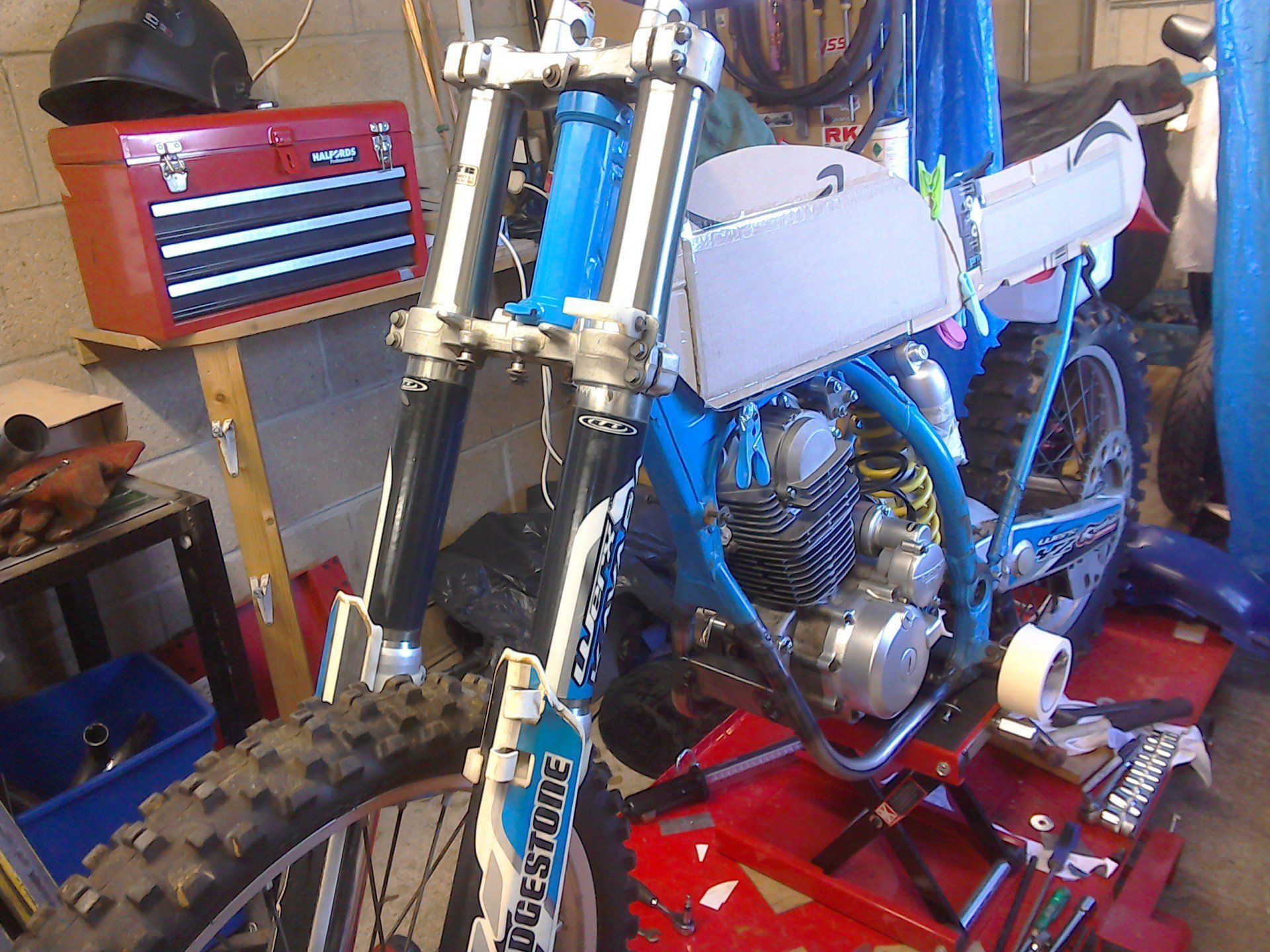
I've slung the suspension and wheels back on, added some cardboard bodywork and propped up the potential new rear mudguard just to see how it might all fit together.
Now, I just need to decide what I'm going to tackle next. I think it will probably be the exhaust.
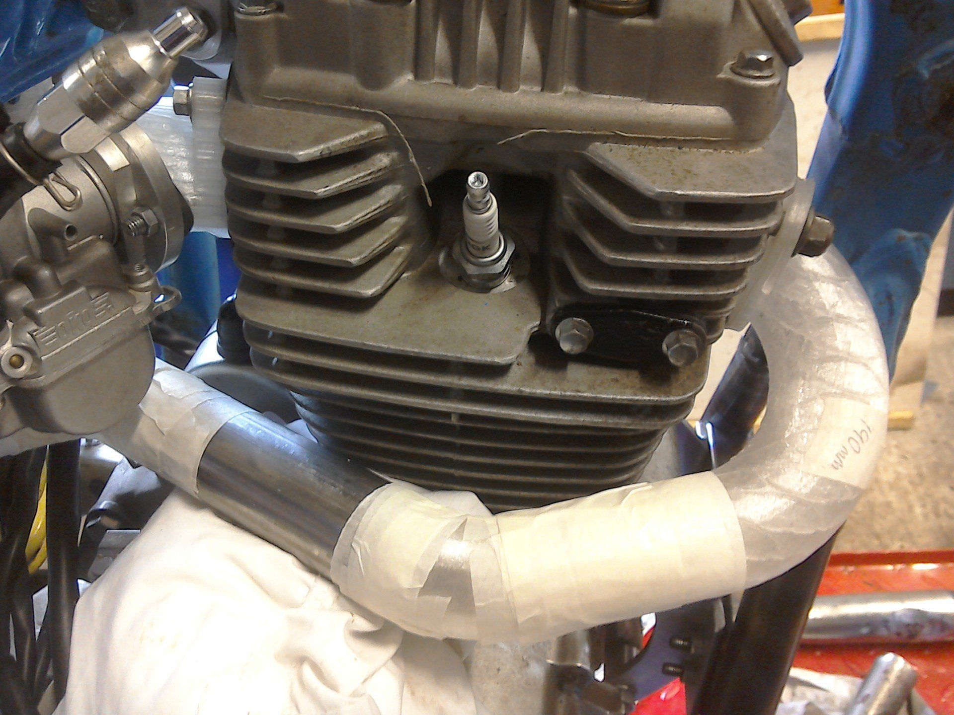
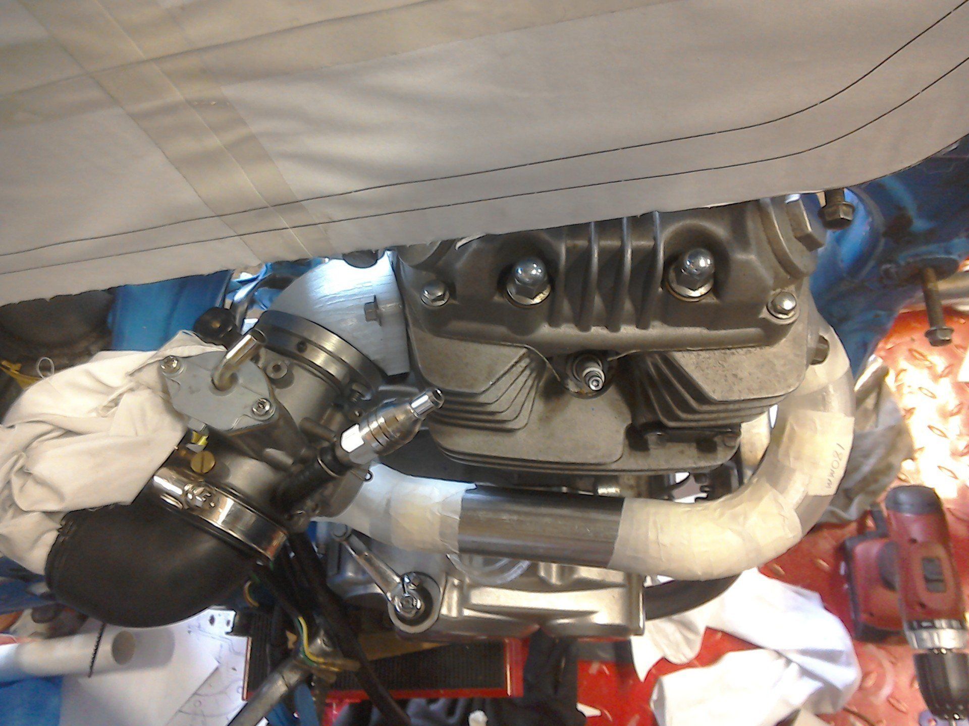
With the engine finally fixed in place, I picked the exhaust as the next problem to solve. I plan to buy pre-fabricated exhaust bends (in mild steel because they are both slightly cheaper to buy and easier to weld with my current equipment). After researching what bends and pipe diameters were easily available off the shelf, I then set to with some paper templates to see if I could get an exhaust to clear the front down tube without it requiring any modifications.
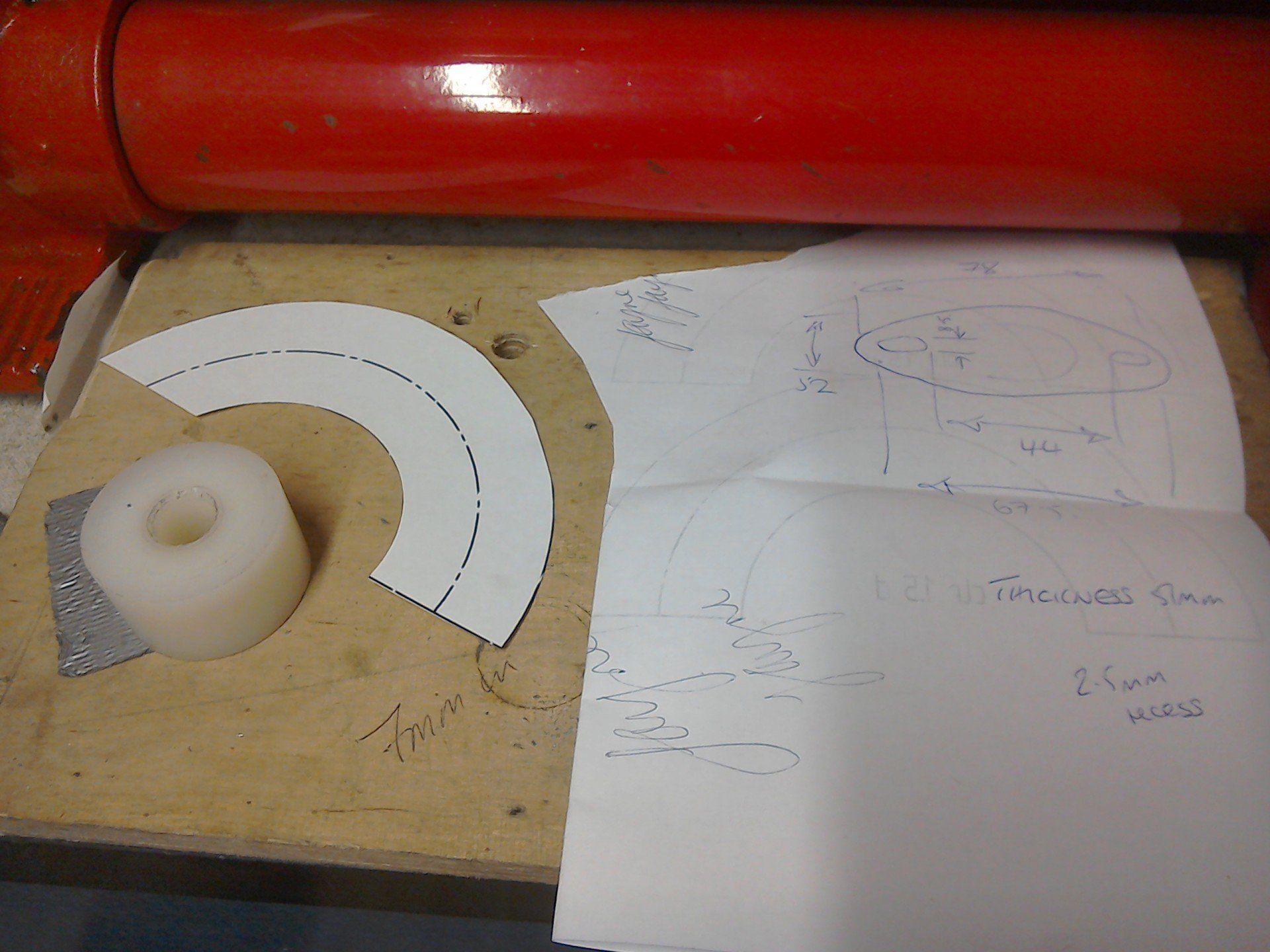
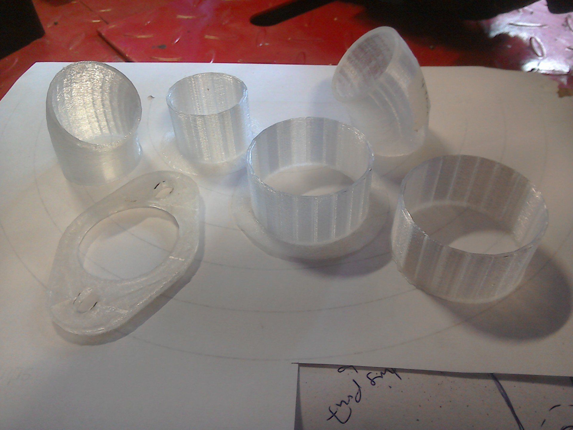
Paper templates proved to be inadequate (they were a bit too floppy!). So, once again, I fired up the 3D printer to make some solid models, starting with the front bend and exhaust clamp.
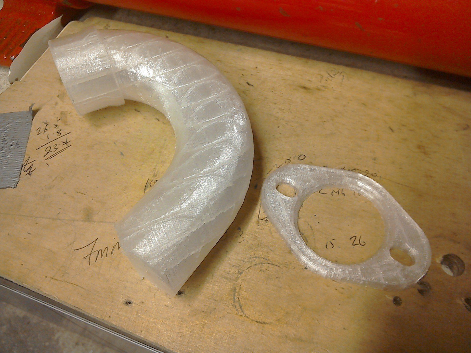
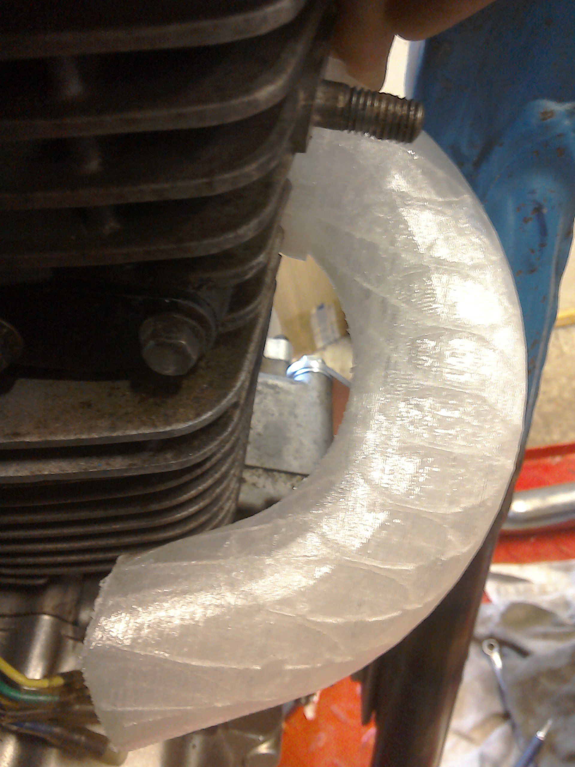
These were much more useful and proved that I could, indeed, get an exhaust on without modifying the front frame tube, but only if was wiggled correctly.
However, whilst the front pipe can indeed be made to fit, there isn’t enough clearance to get the clamp in place. That will need a rethink. It’ll probably need to be some kind of split clamp design.
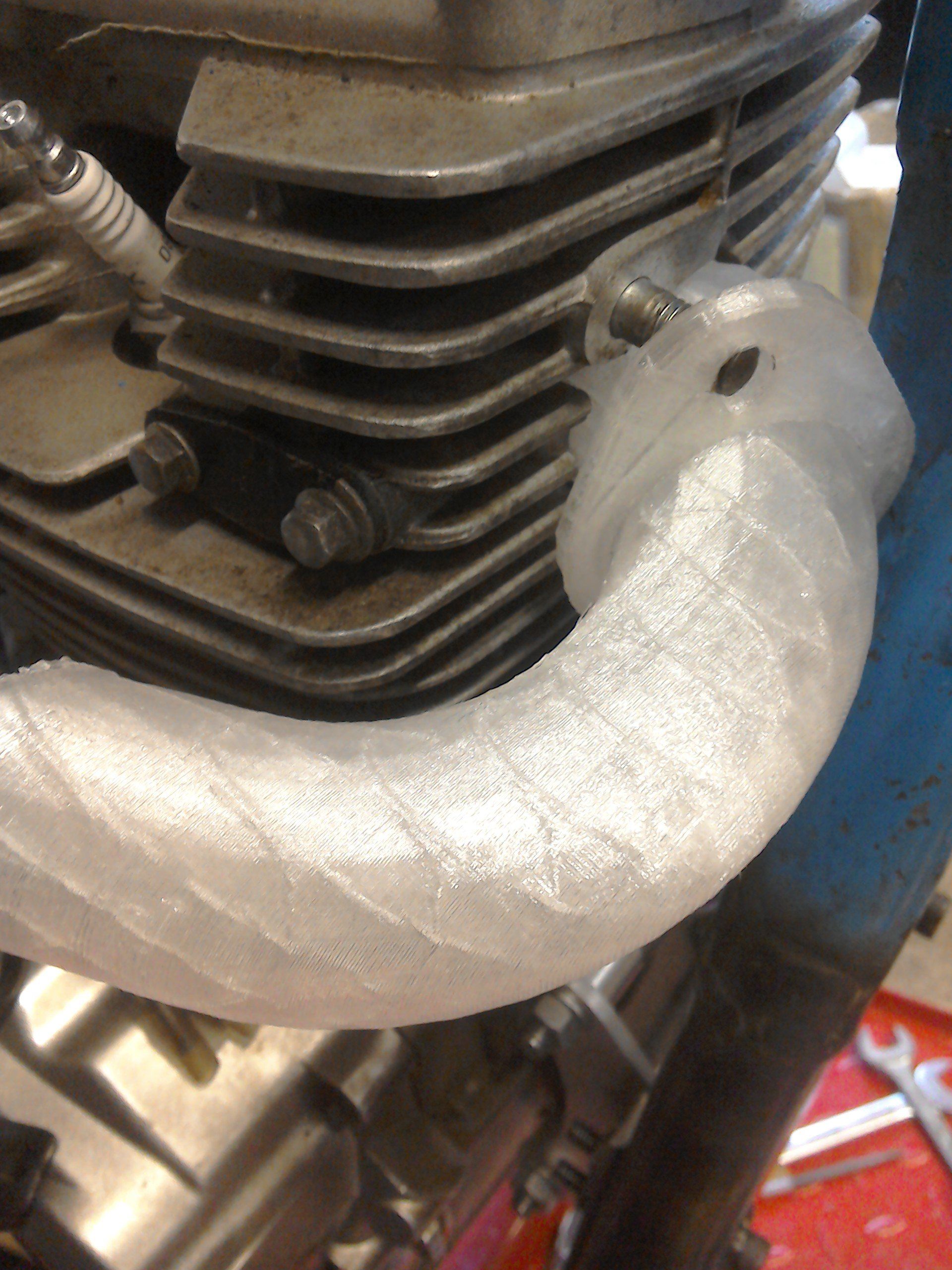
I will need to pay careful attention to where the joints are situated in the full system to make sure that it can still be wiggled in the correct fashion, or it won’t fit.
Whilst the 3D printer was working, I decided to print a variety of different bends. So now I have a kit of bends which I can use to try and fashion into a full prototype exhaust system before I invest in some steel.
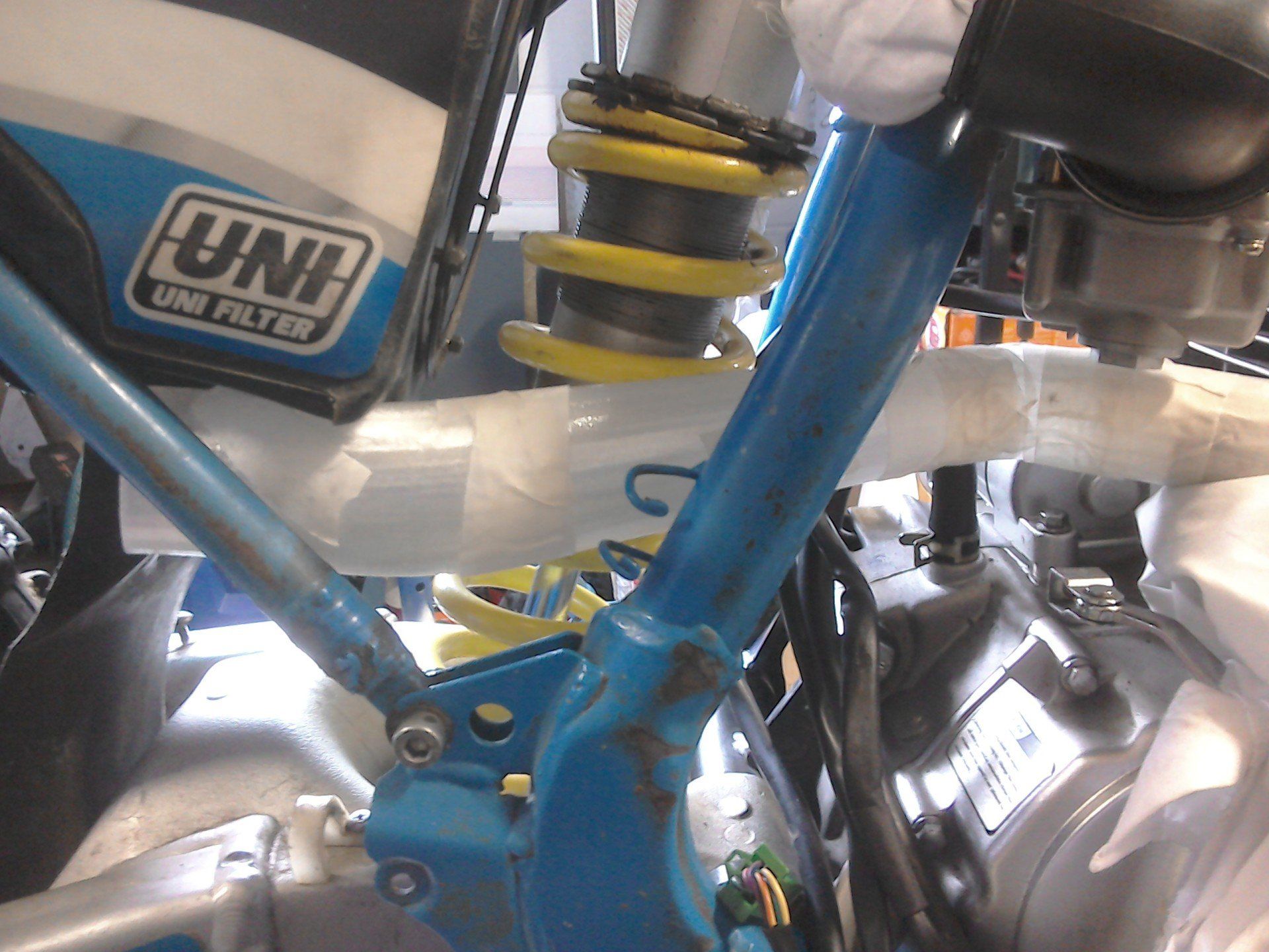
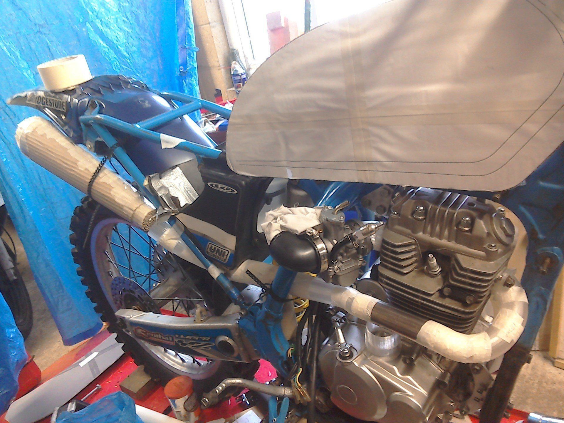
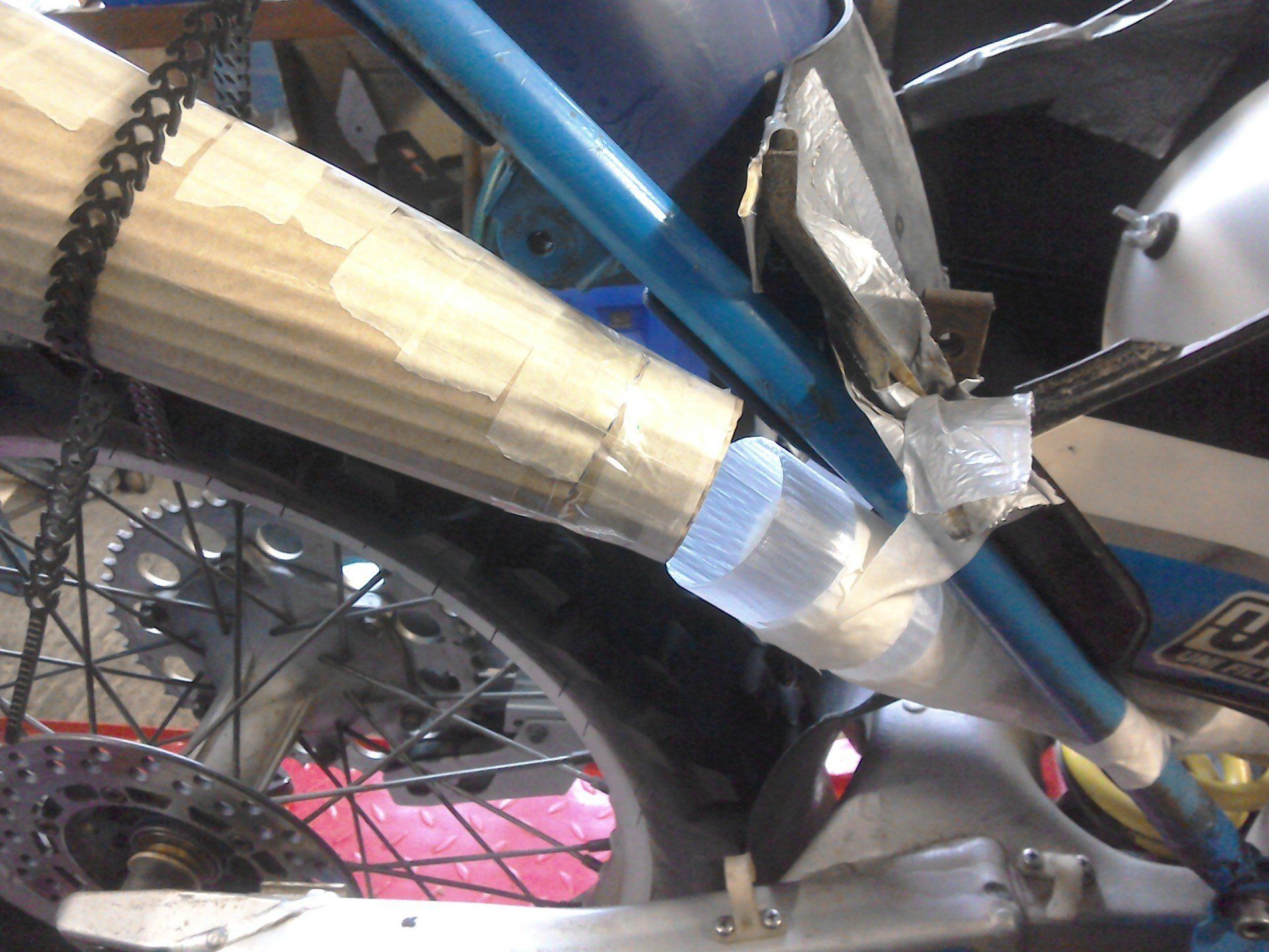
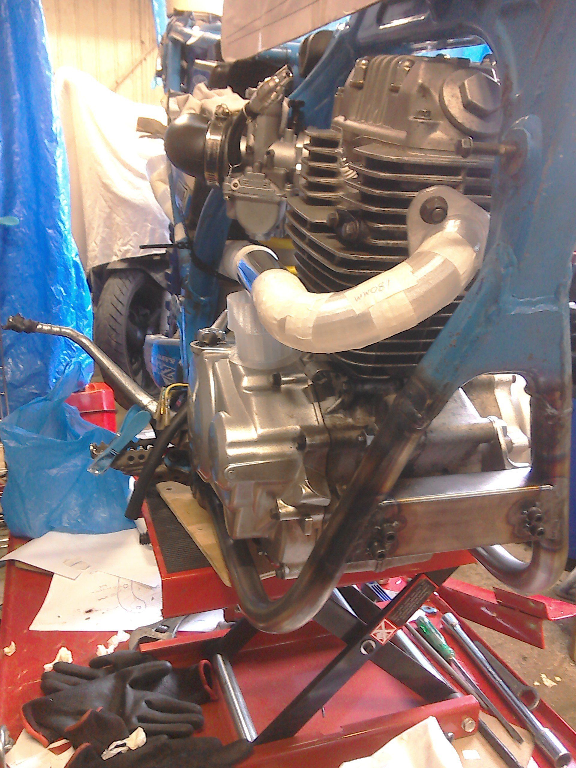
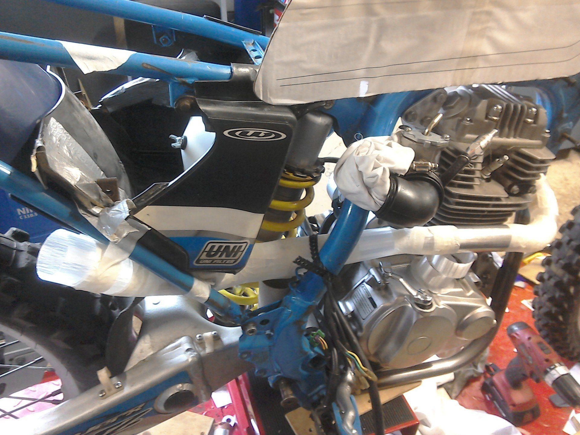
And that's what I'm working on at the moment, working out the route of the exhaust using the 3D printed bends, some suitable diameter tube, and lots and lots of tape to hold it all together!

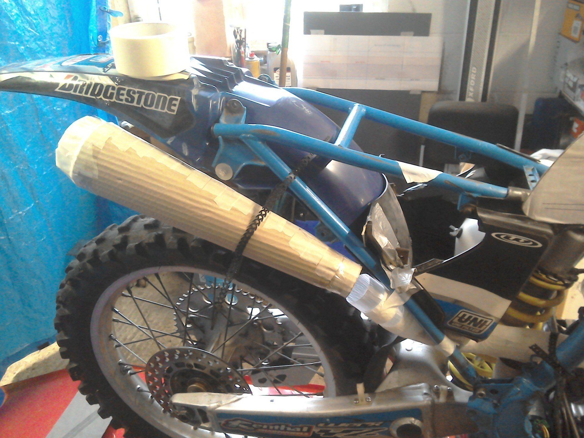
More work on the prototype exhaust system means that the ‘plastic’ exhaust also now has a cardboard silencer!
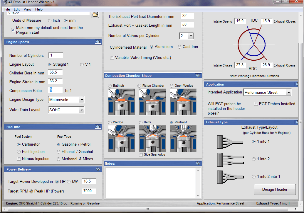
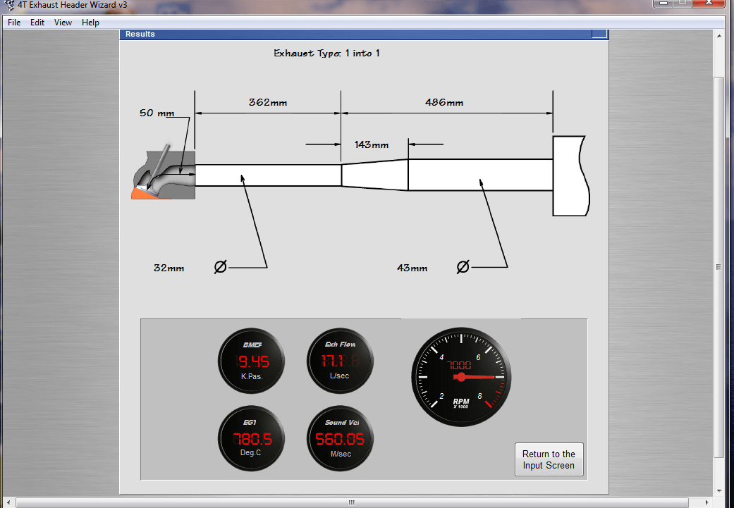
From measuring the old exhaust and taking some numbers from some 4 stroke header design software, I had an idea of the pipe diameters and lengths that I wanted to use. Translating this into an actual exhaust system (even with the help of the 3D printed bends and lots of tape - lots and lots of tape) has been quite time consuming, but I’m somewhere close now.
Just need to get the exhaust pipe to meet up with the silencer.
Here are a couple of example screenshots from the header design software that I used. I've had it for some years, but never used it before to actually build any pipes, so I can't comment on whether it is any good - it was inexpensive though!
The version I have is quite old. I looked at their website recently (https://buildandclick.com/html/all_software.html) and this has been superseded by newer versions for separate engine configurations, rather than the one size fits all version that I own. They seem to be a long way behind on their release schedule for new versions, and those that are currently available are probably less suitable for motorcycle applications. They also do pipe design software for two-stroke engines.
The version I have is quite old. I looked at their website recently (https://buildandclick.com/html/all_software.html) and this has been superseded by newer versions for separate engine configurations, rather than the one size fits all version that I own. They seem to be a long way behind on their release schedule for new versions, and those that are currently available are probably less suitable for motorcycle applications. They also do pipe design software for two-stroke engines.
In hindsight it would have been better to have tried to design 3D printed bends that clipped together (but were still be able to rotate relative to each other) instead of relying on taping the sections together, because, you either find that you didn’t get them stuck in the correct position first time and so have to peel the tape off again (tape which will now be stuck firm) or you did get them in the correct position but this time your tape has decided not to stick at all and it all falls apart! Eventually though, with the help of some props to support everything, the exhaust is taking shape.
After much deliberation about silencer design, the only off the shelf universal ones that I liked were reverse cone megaphones. I wasn’t sure how that would look on the bike and rather than spend money on something that I might not use, I built a cardboard replica to offer up instead. I think it should look Ok.
Hopefully I’ll soon be in the position to buy some bends, and try to recreate the plastic exhaust in metal.