Monday Articles - January 2021
Scroll down for latest instalment
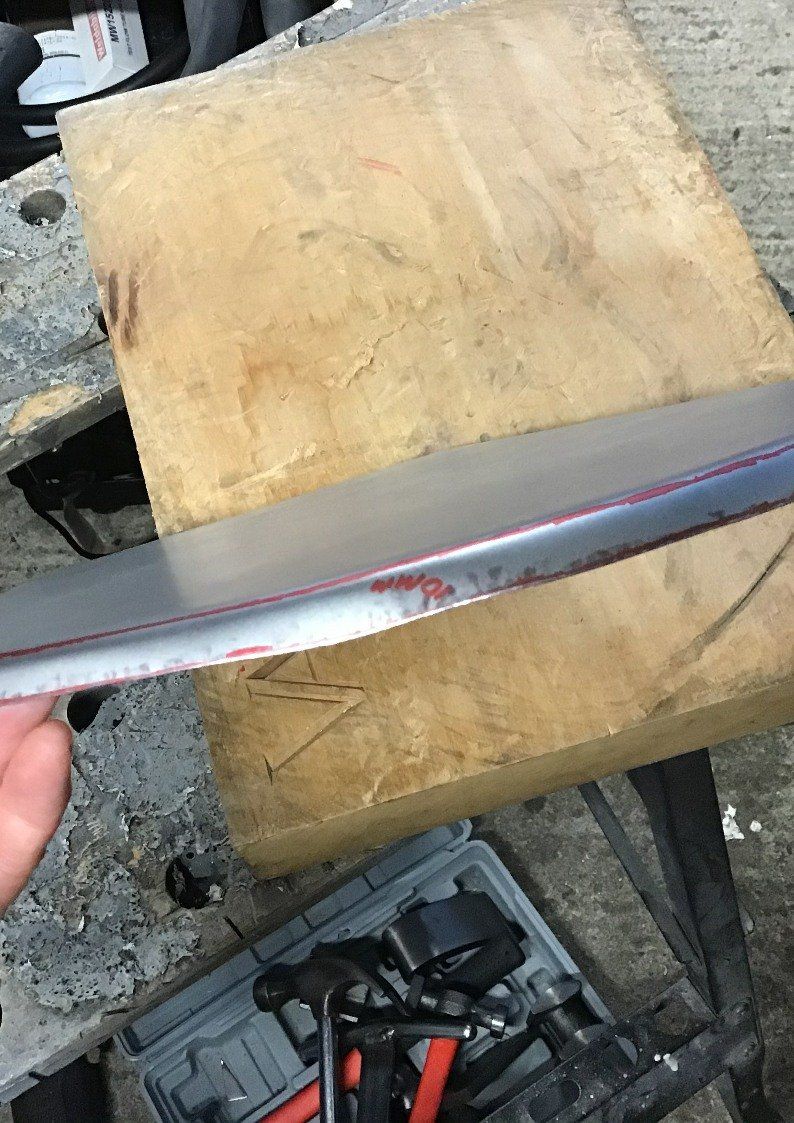
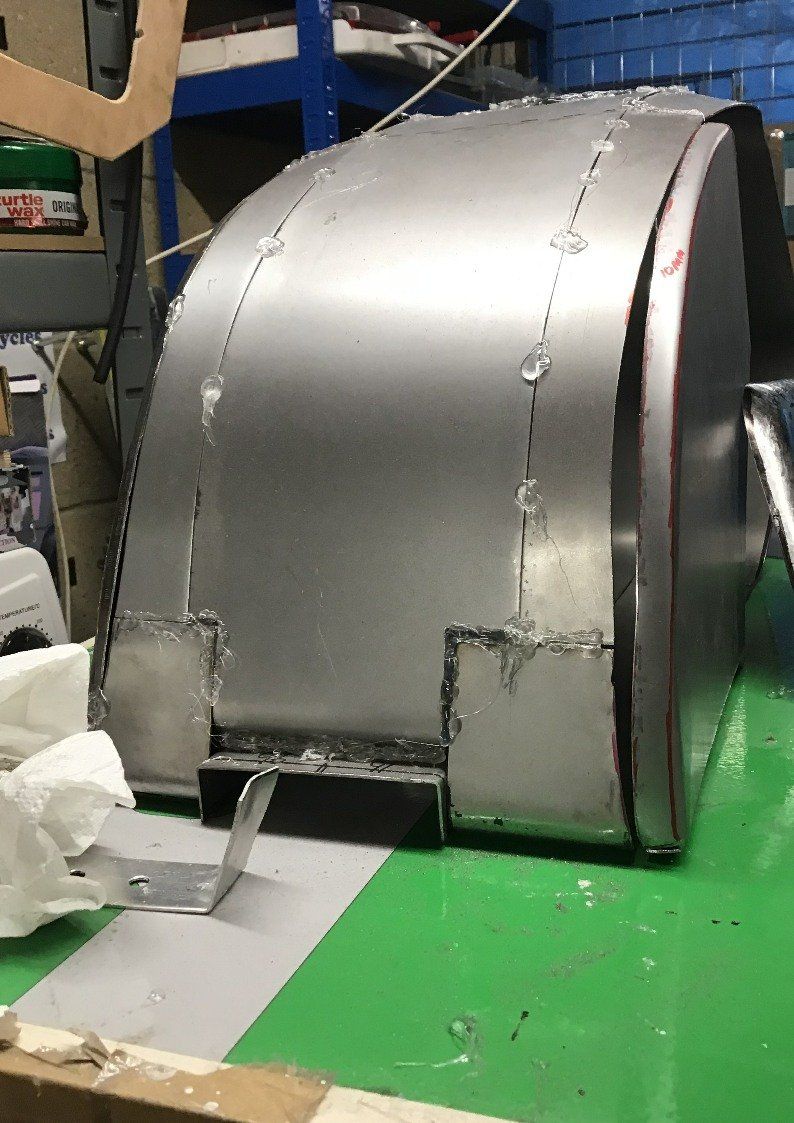
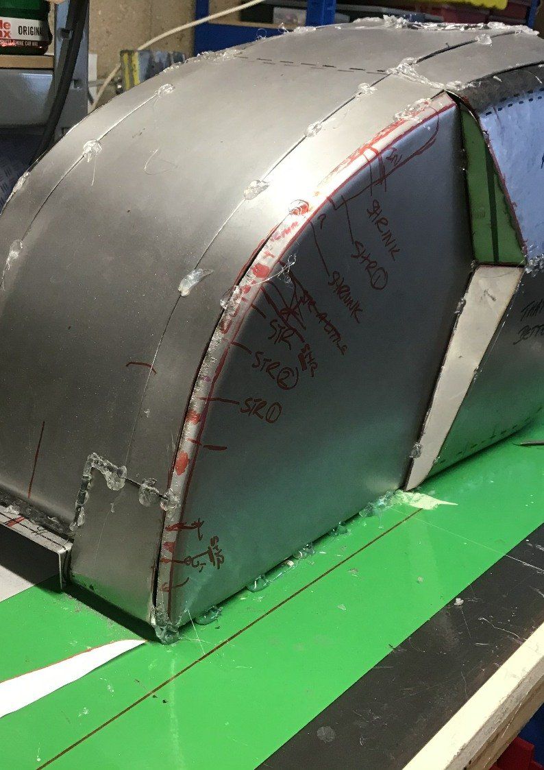
The second side! Well, the start was easy - cut steel using template made for first side, clamp in hammer-form, bash to shape. So far, so good. I did make a small alteration, however. I left a 15mm flange around the edge for the first side, which turned out to be way too wide, so it’s been reduced to 10mm for this side, which should still give a little extra to play with.
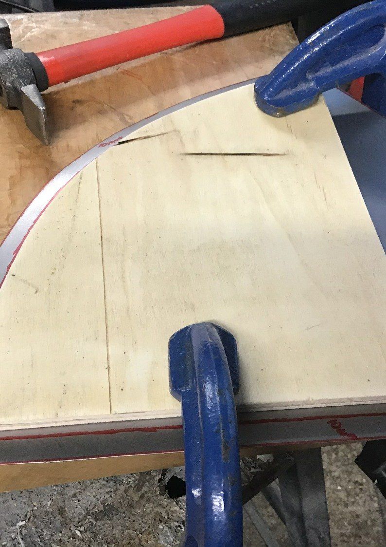
Here it is bashed to shape, and I remembered to bash it the right way! The smaller flange meant that the curved edge didn’t pucker as much, so no blow torch action was required to deal with them, and that also meant that the panel ended up with less initial curve after hammering than the first side.
First trial fit, straight from the hammer-form.
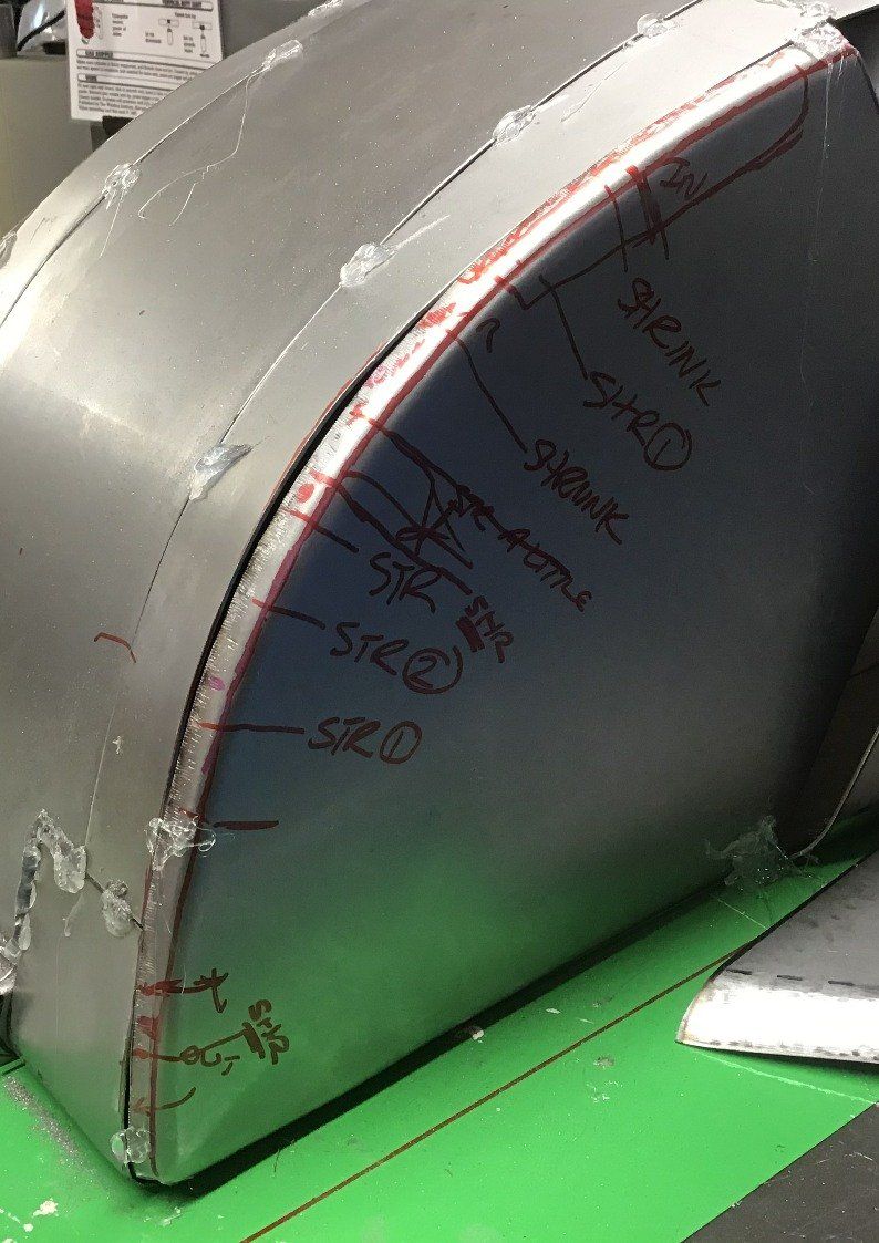
And after some work with the shrinker/stretcher.
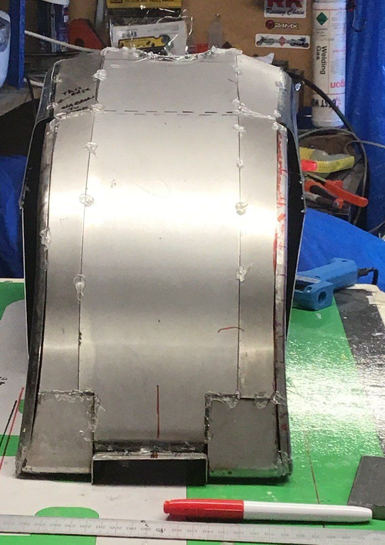
On paper (or screen!) that sounds like a quick and easy process, in reality it takes me hours and you can see by the number of scribbles on the tank side just how many visits were made to the shrinker/stretcher!
Eventually, though, I end up with something that I’m reasonably happy with.
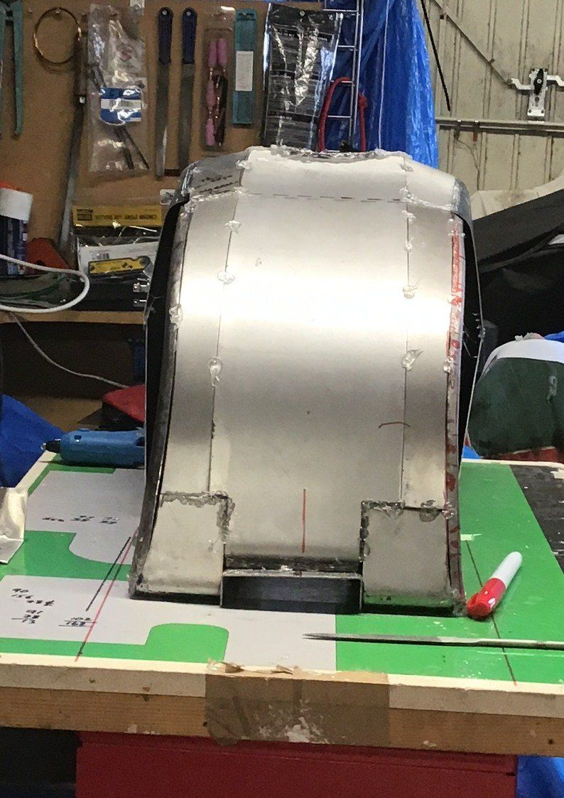
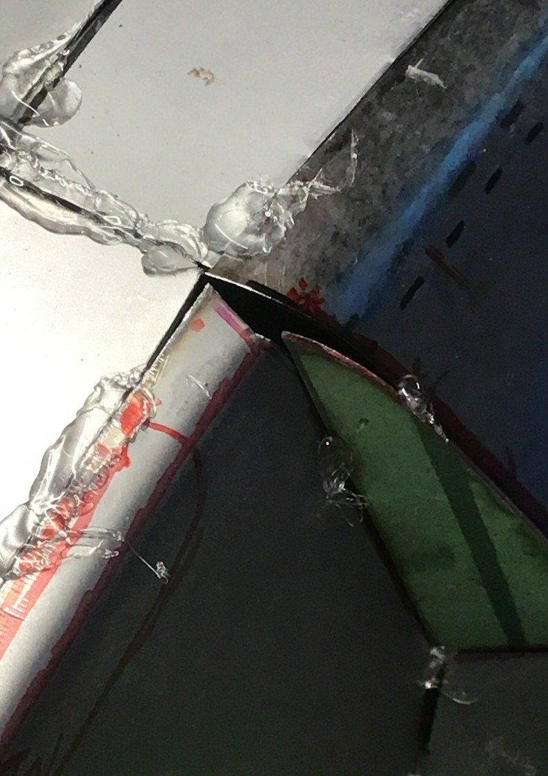
That just left the little infill panels to fit.
And that’s it, all of the pieces of the tank made…
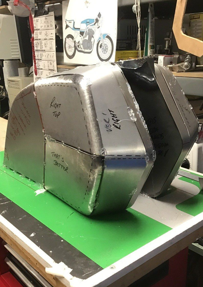
… apart from there are a few gaps that will need attention! But for now, the tank has to wait, I’ve got a more urgent job to finish (Finish! I haven’t started it yet and it’s going to be a nightmare!) which may well be the subject of next week’s missive. In between time, I need to formulate a plan on the welding sequence (and practise my welding of thin sheet steel). But first, I may also see if I can stick the tank together securely enough with the glue gun to actually try a test fit on the bike.
Welding the tank is on hold for the moment as I summon up the courage to actually attempt the job. Instead I’m pressing on with another job that I’ve been putting off for some time - sorting out the rattly GS500.
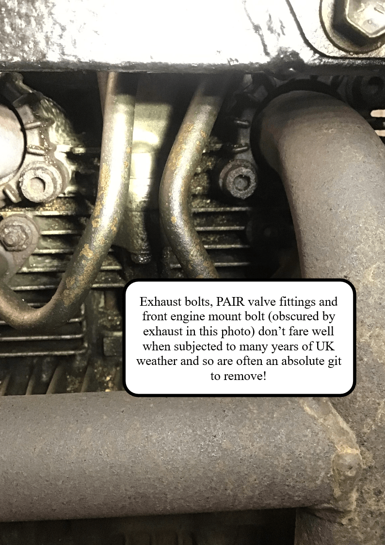
I’ve known for a while that the engine’s condition was less than optimum (understatement!) but it still ran, it was only my winter hack, and if I sang loud enough while riding I could just about drown out the noise. But with the UK in lockdown again (so I couldn’t go anywhere apart from to work and that journey is handled by bicycle) now seemed as good a time as any to sort it out. But one of the reasons that this job had been put off for so long was because I wasn’t relishing the job of removing the exhaust bolts.
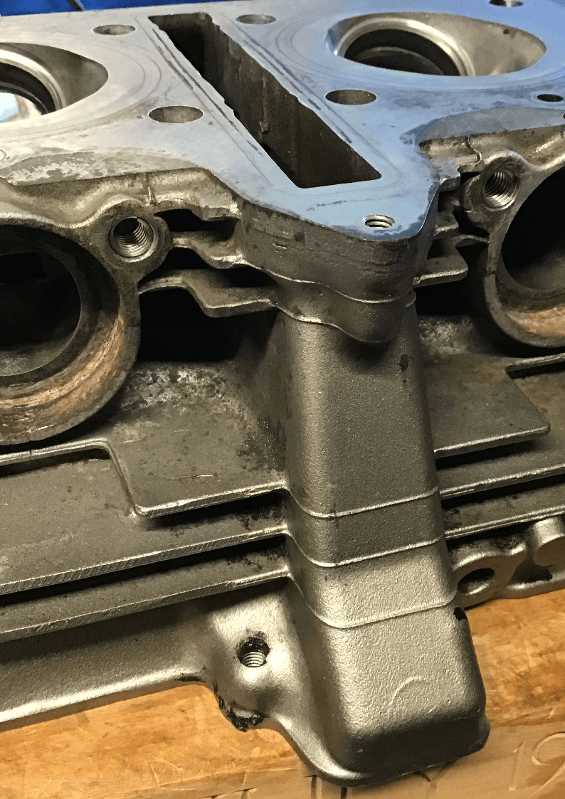
The bike’s seen many an English winter and the exhaust bolts (along with PAIR valve fittings and the front engine mount bolt) are in the direct line of fire of a lot of the crud. As expected, these resisted all conventional means of attack. And so, given that I was planning on removing the head anyway, it was decided the quickest thing to do would be do whip the head off the bolts and then sort the remaining bit of bolt out when the head was on the work bench. The trouble was that there isn’t a lot of access room.
After casting around the garage for a suitable tool to attack the bolts with, I decided to give the flexi-drive that came with a cheap rotary tool a go. I wasn’t too hopeful as it didn’t look terribly robust, but I fitted it up with a carbide burr and gave it a shot.
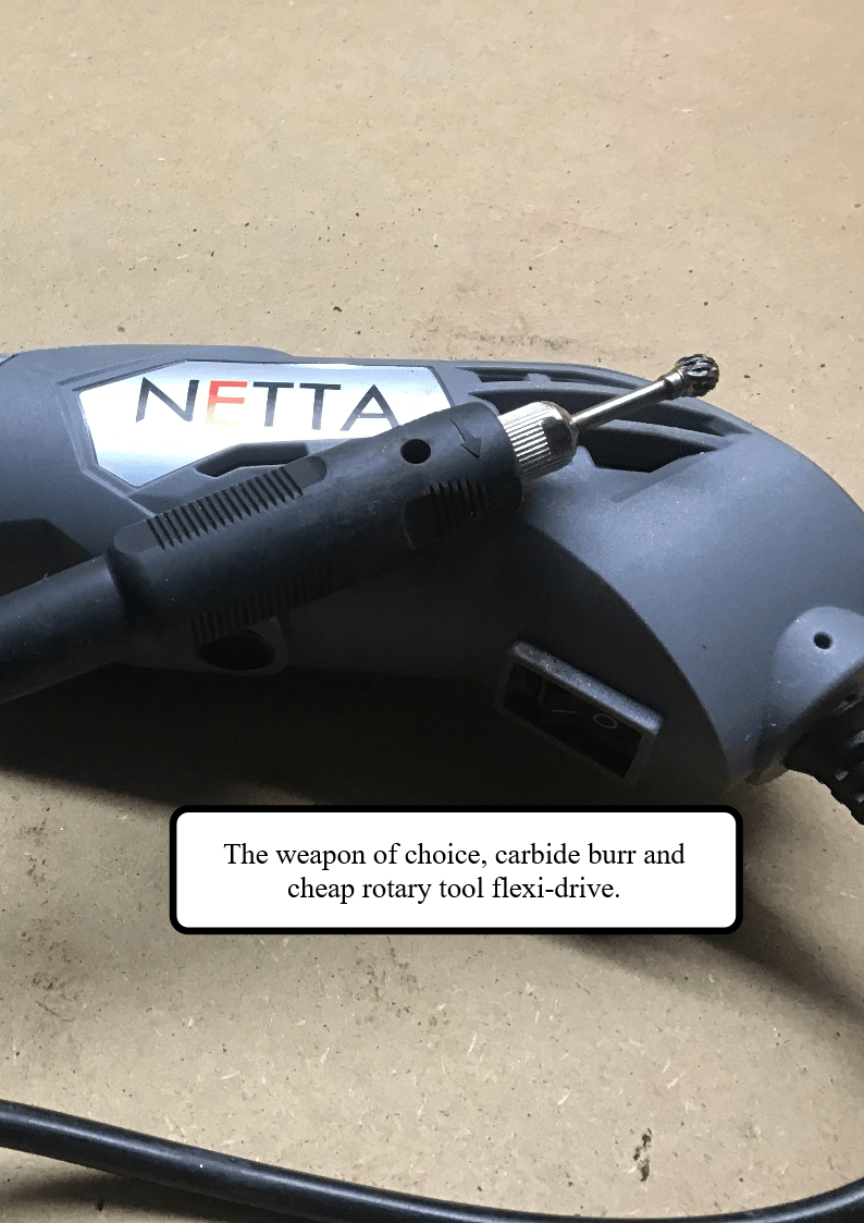
Surprisingly, it cut really well, but the vibration produced constantly loosened the collet’s grip on the shaft of the burr. No amount of tightening would solve this issue, so a new solution was needed. After some thought, I decided to try a little drop of stud and bearing fit on the shaft of the burr. It may well permanently fix the burr in the flexi-drive, but my level of frustration was so high by this stage that I didn’t really care!
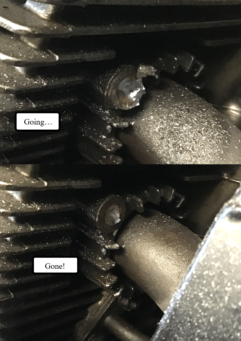
Eventually all four bolts had lost their heads, well actually only three lost their heads. One of them, once a suitable hitting point had been cut, succumbed and was undone using a hammer and chisel to tap it round.
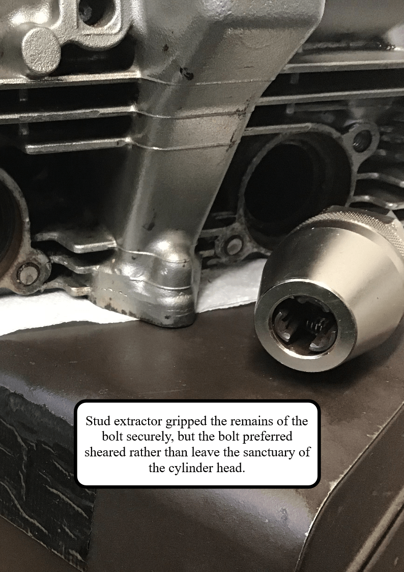
The remaining three, once the head had been removed from the bike, where attacked with a stud extractor. This wasn’t terribly successful. The extractor gripped the remaining stud securely, but unfortunately the bolt material proved weaker than the cylinder head’s grip and so they decided to shear rather than undo. I’ll now have to drill them out, but that’s a job, and a story, for another day…
NOTE: Both the Haynes manual and the official Suzuki manual claim that you can remove the head with the engine in the frame - in reality, this may prove difficult (or even impossible!). For models fitted with the PAIR valve, you will also need to remove the associated pipe work if you want to remove the cylinder as well with the engine in the frame.
And no, I haven't yet tried to remove the burr from the collet.
Last week my trusty old GS500 lost its head, shortly followed by its cylinder and pistons, and now (with the aid of many bits of other GS500 engines acquired over the years) hopefully two reasonable healthy engines will eventually be built up. One for the everyday runabout, and one to be kept as a spare.
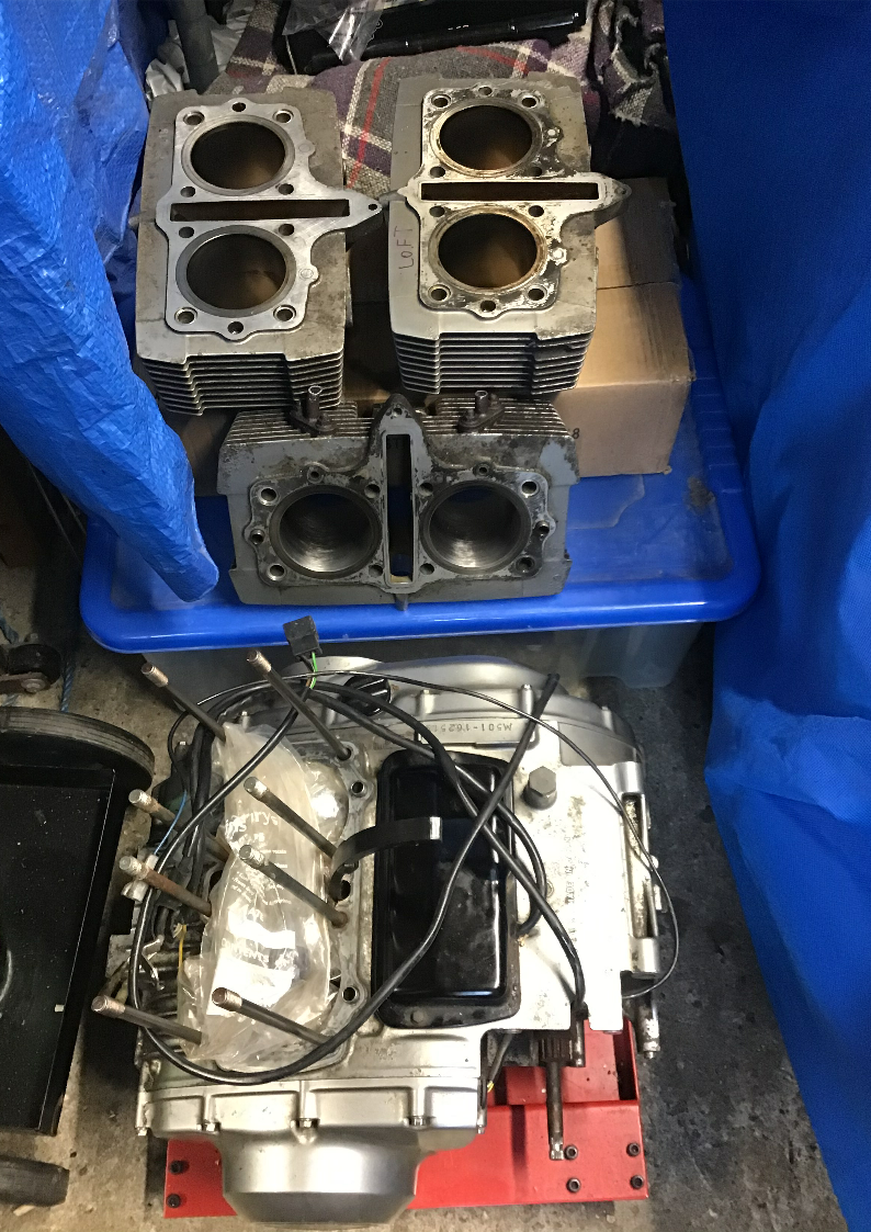
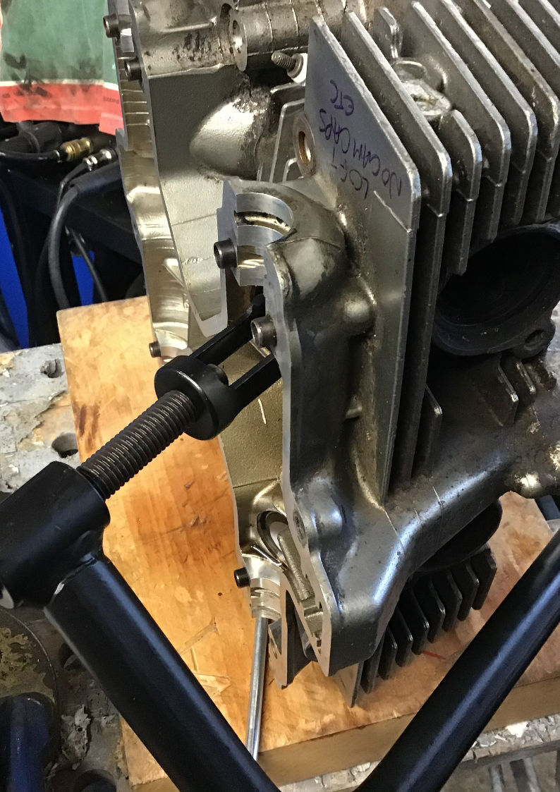
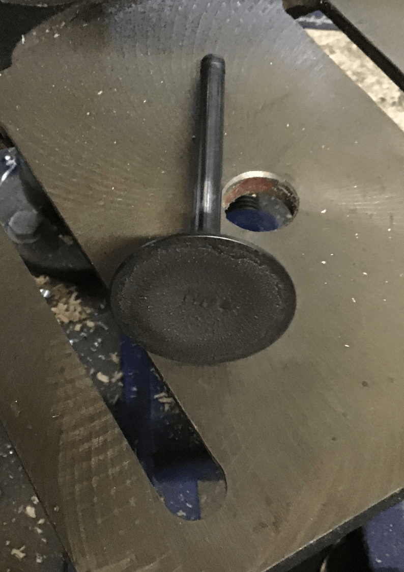
The result of my hoarding of spares means that I now have four cylinder heads. One of these is effectively scrap as it doesn’t have its matching cam caps, and so, because I’m not used to being this deep inside a four-stroke engine, this one is being used as the guinea pig, before I move on to to try and do the job properly on the good heads. First job, then, is to get the valves out using my freshly purchased (cheapie) valve spring compressor.
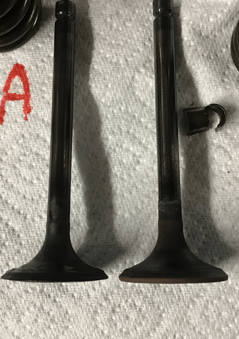
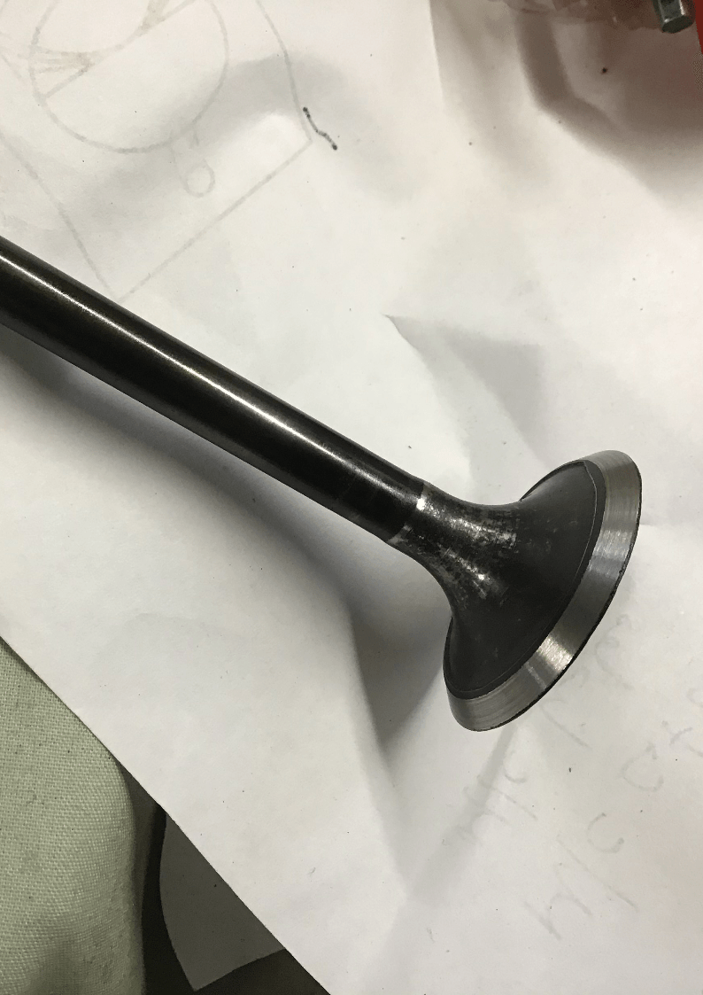
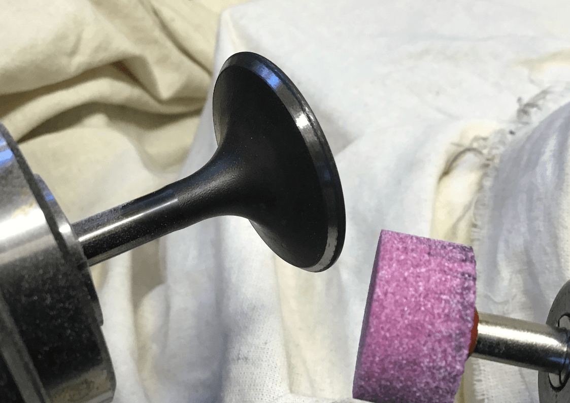
Even my limited four-stroke knowledge tells me that the valve on the left is scrap. The one on the right probably has some life left in it but would need refacing.
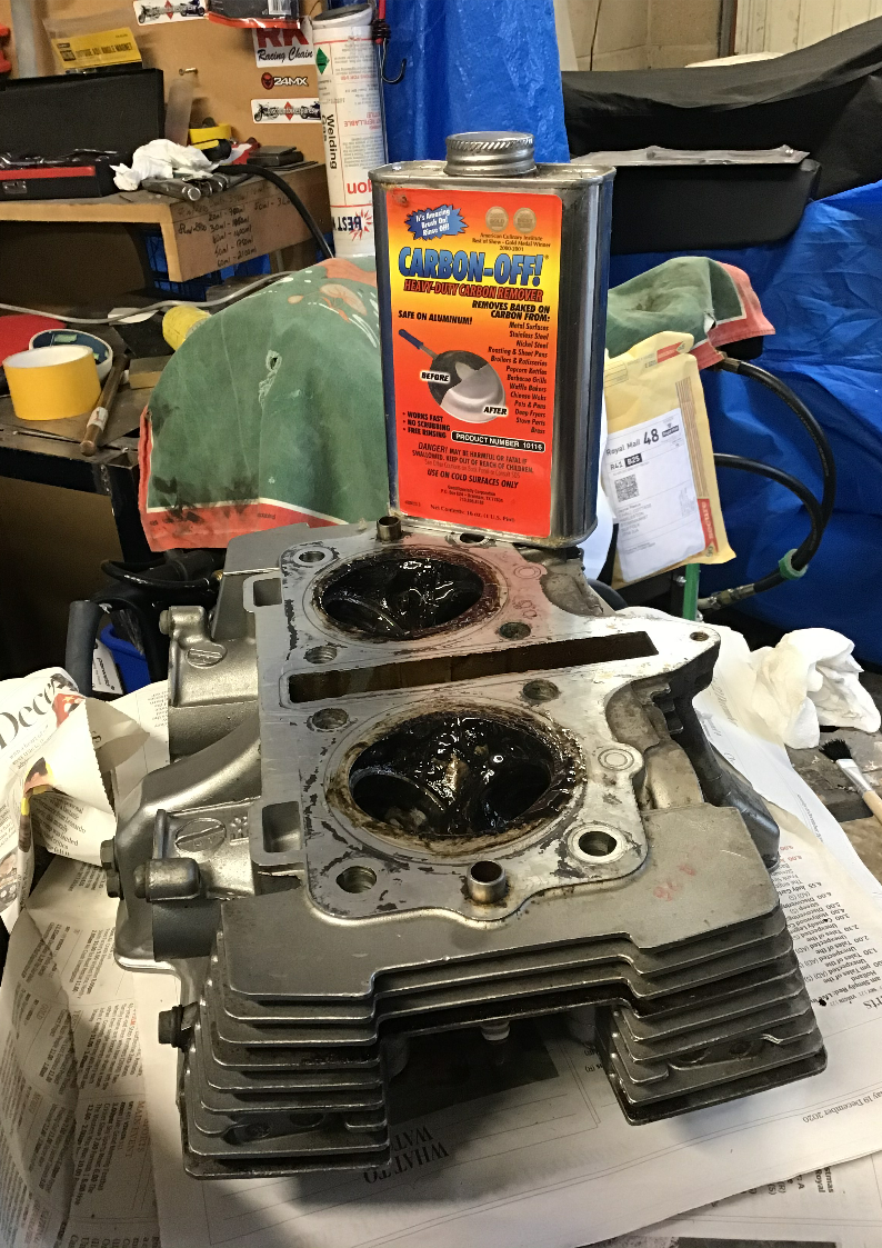
To remove the carbon from the head, without having to resort to scraping, I tried this ‘ Carbon Off’ gunk. It’s designed to clean kitchen utensils, but it’s safe on aluminium, and I’ve used it before on bike parts, but I still tried it on the scrap head first just to check nothing untoward happened. It did the job, but I had to leave it for several hours. To be fair, though, this tin is several years old now, so the stuff may have been past its best.
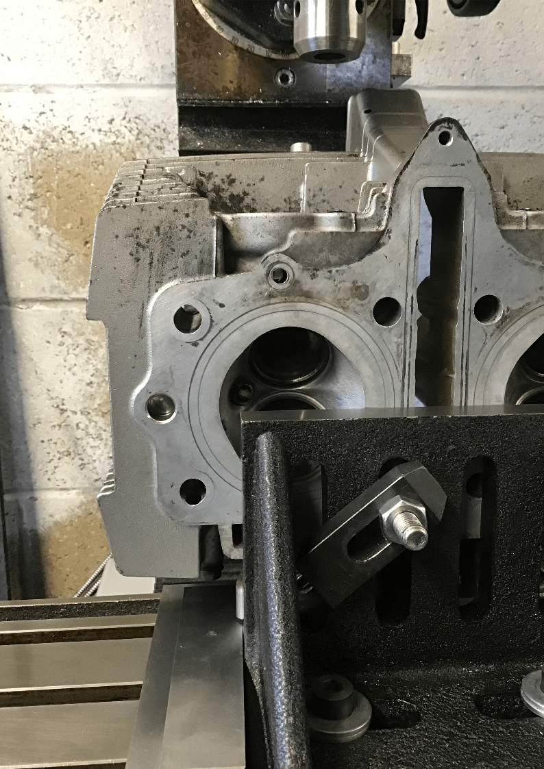
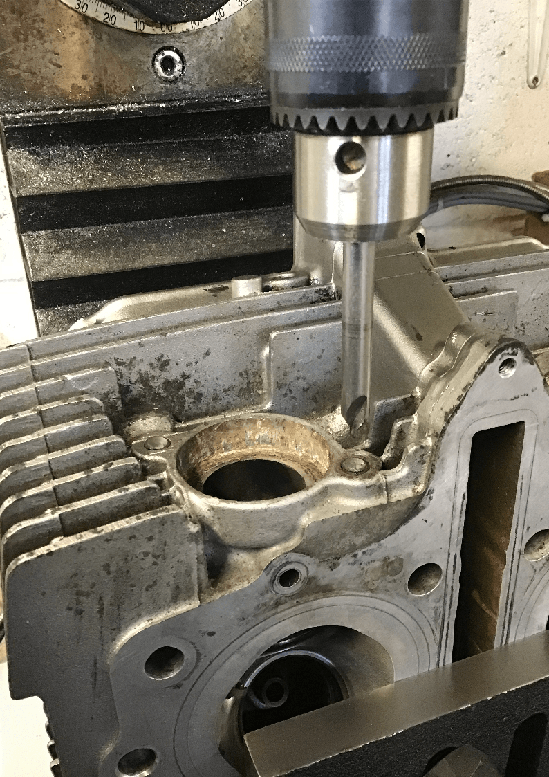
Next up was attacking the snapped exhaust studs. Luckily I have access to a small milling machine which is just big enough to accommodate the cylinder head. If you’re clever, you can drill out the old thread with progressively bigger drill bits, right up to tapping drill size / root thread diameter. Then all you have to deal with is the remains of the thread which you may be able to pick out or move along with the aid of a suitable tap. To do this successfully, though, you need to make sure that you’ve picked up the exact centre of the bolt, which is often easier said than done.
Once you’ve got a hole through the bolt, you could try stud extractors, which have a left handed thread. The idea being that eventually, the extractor will wedge firmly in the hole and further tightening will cause the bolt to undo. I’ve never had any success with these and should the extractor snap in the bolt, you enter a whole new world of grief.
Another method, once you have a suitable hole, is to whack in a torx or star bit and then use this to try and undo the bolt.
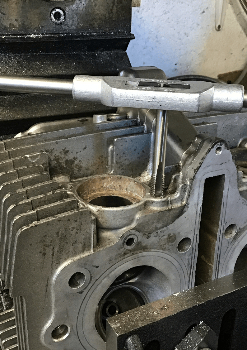
Because I already have an M8 thread insert kit, I went straight for drilling a smallish hole as near the centre as possible, then machined out the entire bolt with a slot drill (the previously drilled hole gives the slot drill an easier time and the rigidity of the slot drill means it doesn’t follow the pilot hole should it have wandered off course.) Then it’s a matter of using the drill and tap included in the thread kit to prepare the hole for the insert.
If possible, always centre drill a hole position first. Centre drills are more rigid than a standard twist drill and you’ll stand a much better chance of getting your hole where you really want it.
When tapping a hole, it’s important that to make sure the tap is entering the hole squarely and remember to take it carefully and back up the tap occasionally to break the chips. Take it slowly, use cutting fluid and try really hard not to break the tap!
Thread inserts fitted, and so the exhaust will be able to go back on - once I’ve sorted cylinder, pistons, valves, bought some new bolts etc. etc.
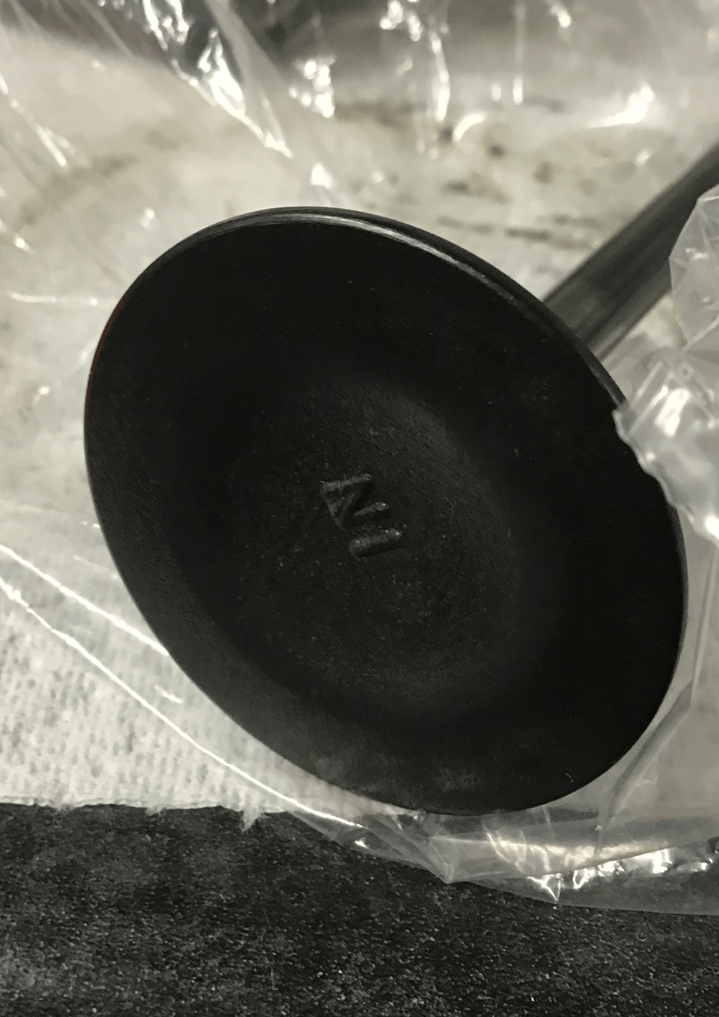
Valves needed to have the carbon cleaned off. I tried this one with a wire brush, but it had very little effect.
So I then tried coating it in the Carbon Off stuff. This didn’t shift it either, but did seem to make it easier to scrape off, so maybe it softened it a bit. Eventually we had a much more presentable valve.
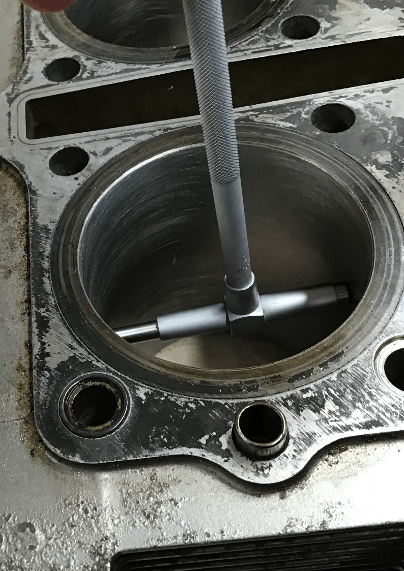
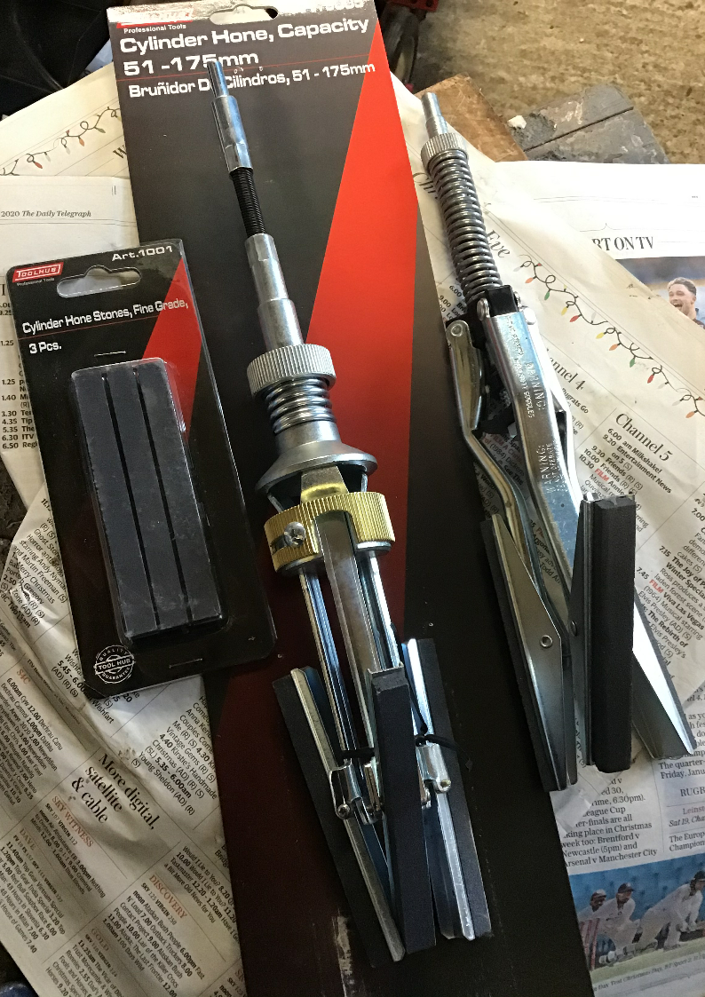
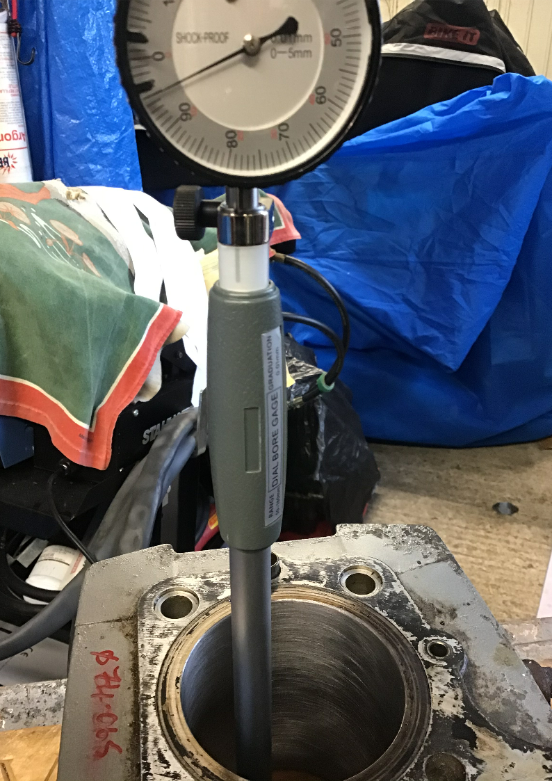
Ignore that silver implement down the bore, it’s a telescopic bore gauge and we’ll come back to it later. What this picture is showing is a disaster caused by a flexible hone and my lack of skill / knowledge.
The Haynes manual suggests de-glazing the bore with a flexible hone if new piston rings are going to be fitted. I had a flexible hone, it’d been sitting on the shelf unused for years. Might as well give it a go then, I thought. That turned out to be a mistake.
Things I didn’t know then:
1) There’s an adjuster knob that adjusts the force with which the hone’s stones are pressed against the cylinder walls. Mine had been screwed up to max.
2) Getting the correct honing pattern by hand requires you to move the hone up and down the bore at the correct speed. This takes some practice and, if you have your drill in the high speed range, you will have to move extremely quickly! Use a low speed.
3) The stones in my hone were far too rough for this application, but manufacturers often don’t specify grit size, they just use coarse, medium or fine and one man’s medium is another man’s coarse. The upshot of this is that I turned a perfectly good cylinder into a scrap one. Still at least I had one I could now practice on!
If you’re going to hone, think carefully first.
I bought a new hone. It came with medium stones, but there were also fine stones available so I bought those too. After some practice on the scrap cylinder, the others were honed using the fine stones.
Old and as it turned out, too coarse hone, on the right. Shiny new one with replacement fine stones on the left.
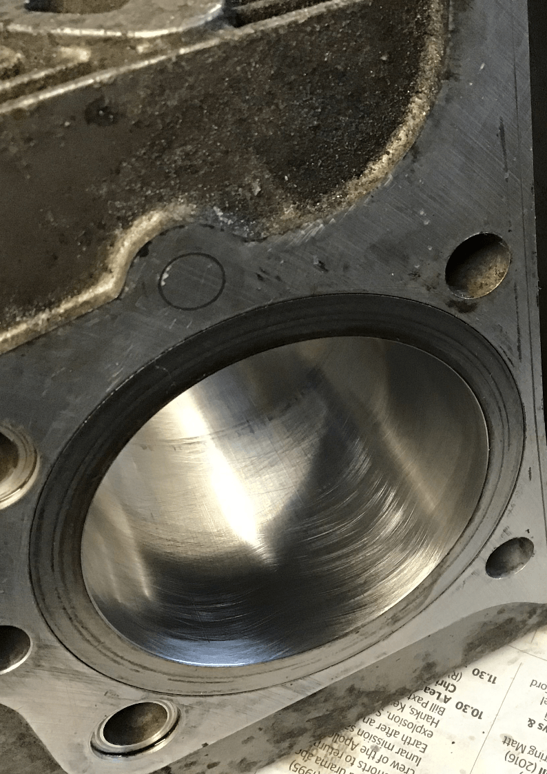
A first pass with the fine hone. Need to get the up and downy speed better, but having already scrapped one cylinder, at this point in the process I was extremely nervous about doing the same to this one.
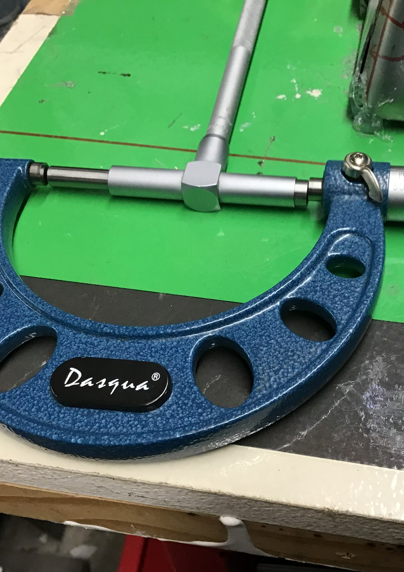
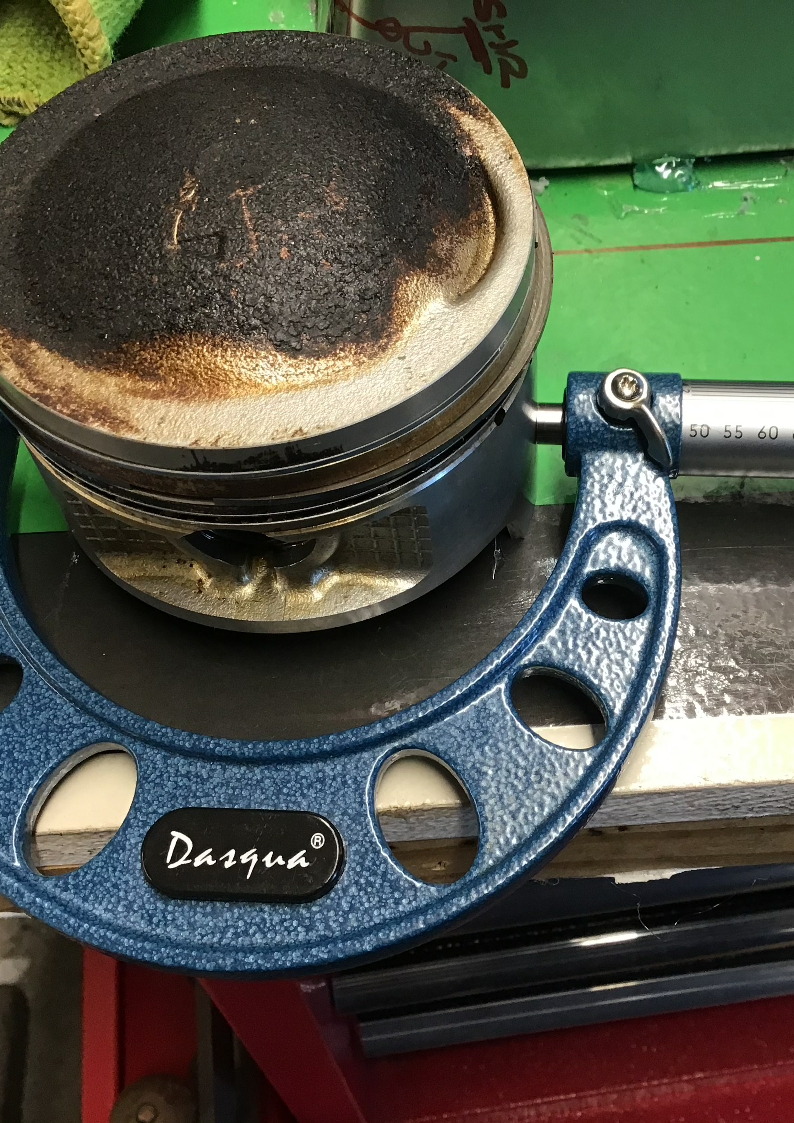
Back to the telescopic bore gauge thingy. It’s used to measure the cylinder bore, but it’s no use on its own, you’ll also need a micrometer. Telescopic bore gauges are fiddly things to use accurately. You need to make sure that they are both centred and square in the bore, and they need to stay that way while you tighten the clamping screw at the top. It’s very easy to move the gauge slightly when doing this and given that Suzuki’s bore specs are measured down to 0.001mm, that little movement counts.
This chap is a dial bore gauge. They used to be horrendously expensive (the big brand name ones still are) which was why so many bore measurements were done using the cheaper telescopic gauges. Nowadays the price differential for hobby use quality gauges isn’t that great.
These are much easier to use. You’ll still need a micrometer, but this time you use it to set the bore gauge to the nominal cylinder size. The dial will then show how much over (or under) that nominal size the bore actually is. The design is self-centering. All you have to do is rock the gauge gently in the bore, find the minimum deflection and read the value off the dial.
Then using your trusty micrometer once more, you can measure the piston diameter. Taking piston diameter from bore size will give you the bore to piston clearance. You’ll need to check bore diameter, piston diameter and clearance are with factory specifications.
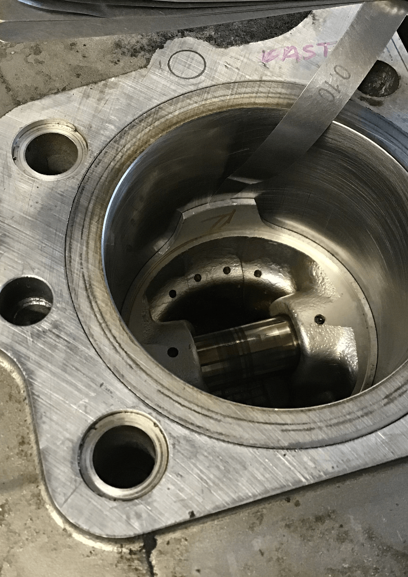
Measuring tools are expensive and the following is absolutely not the correct way to do things but, ultimately the bore to piston clearance is the figure you really need to worry about. You can obtain a rough and ready figure for this using feeler gauges.
Pop piston down the bore it’s going to run in (ideally having first removed the piston rings) and check the gap at several different points. I did this just out of interest and the results correlate pretty well with those obtained using the fancy equipment.
Once again I’ll tell you this is
not the way you’re supposed to do it. There are all sorts of reasons given for why you shouldn’t do this, and if you were building fancy race engines or working on your expensive pride and joy, you certainly wouldn’t do it this way. But, if you’re tinkering with a cheap bike, you’re on a budget and you can’t buy or borrow the correct kit, well…
After some success last week using Loctite to hold a burr in a chuck, I thought I’d try the trick again and see if I could use it to help remove the studs for the oil filter cover (which needed replacement as the threads were a little tired). If I could remove and then replace them one at a time, I could do the job without having to dump the oil. This was partially successful, removing one out of three.
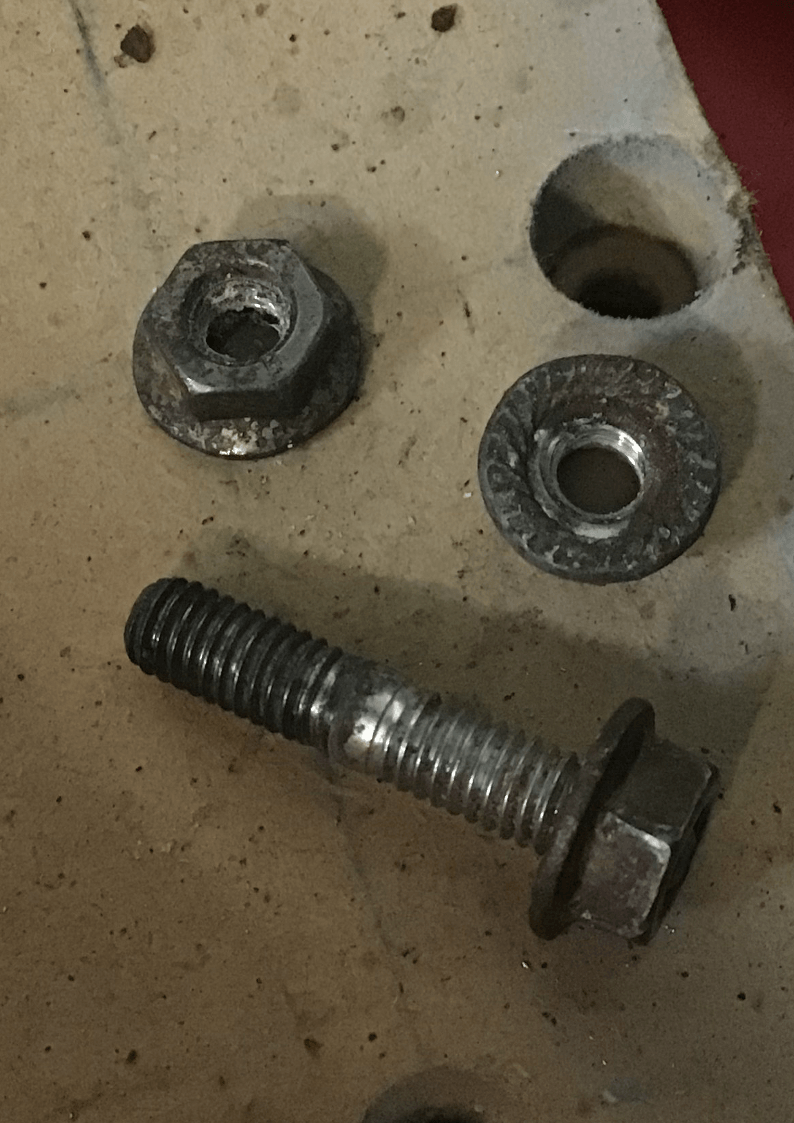
So I found some nice shiny new nuts, which I hoped the Loctite might grab more tightly, and we’re having another go on the remaining two. I’ll let you know how that goes next week.
It’s been a busy week! I also had a go at DIY valve refacing, using a collet to hold the valve in the lathe and a 3D printed fixture to hold an air operated die grinder. I did my first test using the very knackered valve pictured earlier. Whatever happened, this valve was never going to be used again, so it made a good practice piece. Like measuring piston to bore clearance using a feeler gauge, this is not the correct way to do things, but I do like to have a try for myself.
First results were encouraging. I have a few refinements that I’d like to try. Luckily I have also acquired quite a lot of GS500 valves, so I have a few more play with!
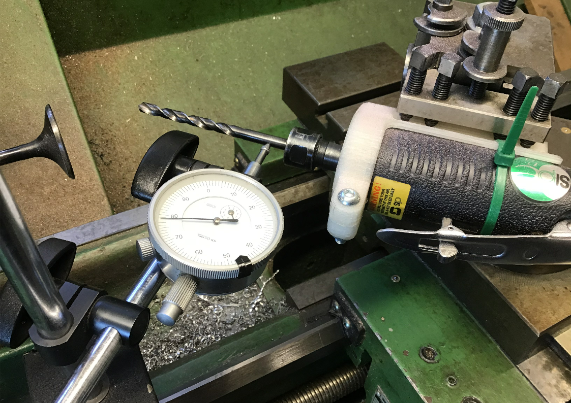
After last week’s promising first attempt at DIY valve re-facing, which consisted of nothing more than stuffing the valve in an appropriately sized collet, bodging the die grinder to the lathe’s toolpost, guessing the angle and plunging in, this week I decided that I’d set it up properly, and then I started to wish that I’d paid more attention in maths lessons, particularly trigonometry and geometry…
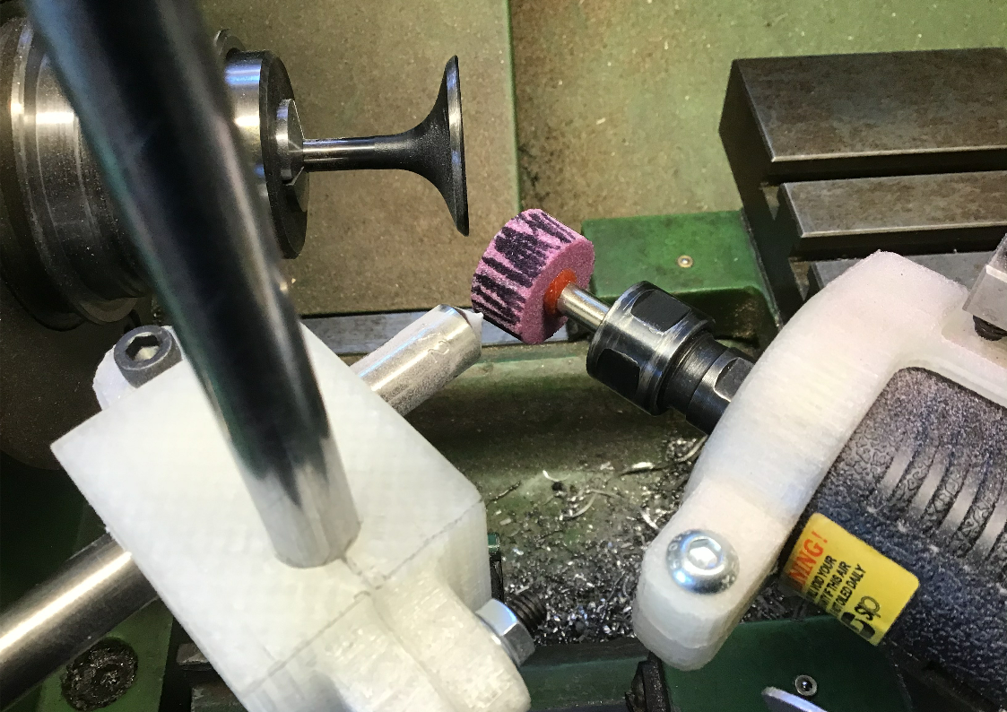
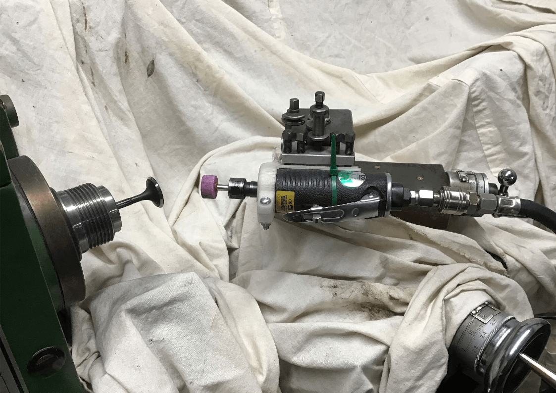
First off, a new 3D printed die grinder holder was required. The Mk2 version was a little longer in the body and incorporated provision for clamping the back of the die grinder - I added a hole for a cable tie!
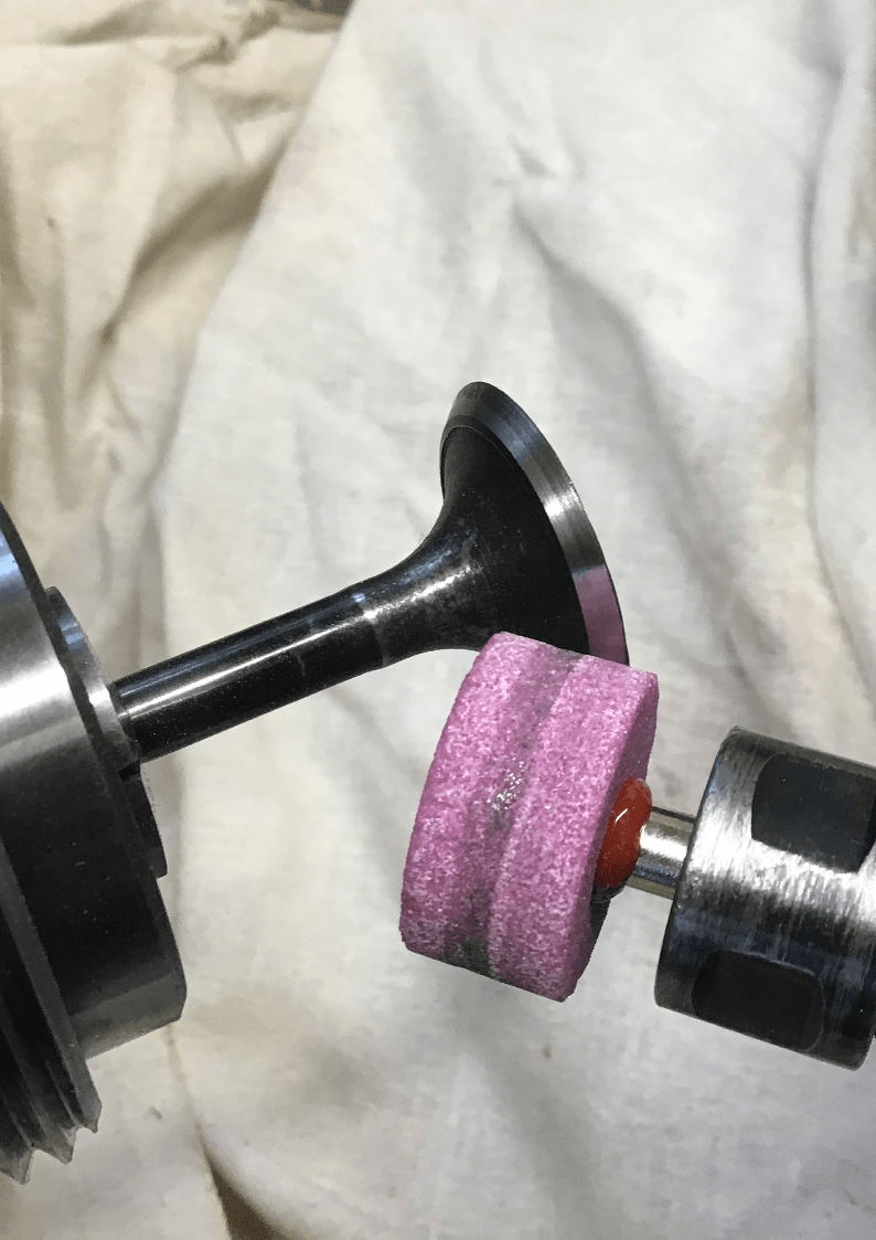
The top slide also needed to be set at the required 45 degree angle, and rather than rely on the graduations on the lathe, I clocked this up using a dial gauge and some trigonometry. On the trial valve I did last week, I ground the valve by plunging the grinding wheel in using the cross feed hand wheel. This time I wanted to put the depth of cut on using the cross feed, but then feed the wheel across the valve surface using the top slide.
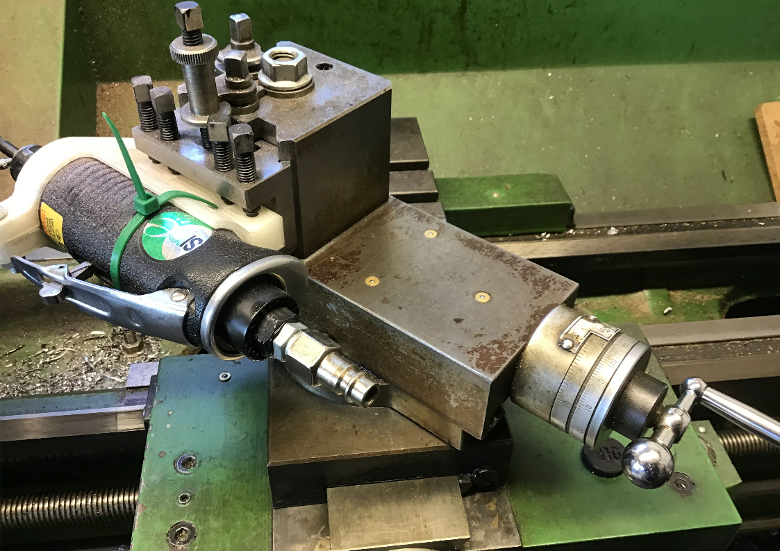
Next I needed provision to dress the grinding wheel so that it was nice and flat. Another 3D print was used to attach a diamond dresser to a magnetic stand.
I thought I was ready to go, and so fired up the air compressor and started with dressing the wheel. This was where I encountered my first problem, for I was not getting a nice parallel cylinder, but a slightly tapered one.
It took a little while for me to cotton on to the fact that I needed to make sure that the spindle of the grinder was running parallel the top slide. It’s not something that you have to consider when the toolpost is holding a lathe tool!
Once I understood that, I used the dial gauge and the stem of a suitably sized drill bit to provide a surface for the gauge to run on, and carefully altered the angle of the toolpost until everything was in line. Now I could true up the grinding wheel with the diamond once more and start grinding a valve.
The valve after a couple of passes, there’s still some areas that haven’t cleaned up so another pass will be needed.
A quick note about speeds / feeds etc. The lathe was running at 600rpm, in reverse so it was contra rotating to the die grinder. The die grinder was running at whatever speed my paltry compressor could manage. Frequent stops were required to allow it to build pressure back up.
Depth of cut (controlled by the cross feed) was around 0.04mm (the smallest graduation on my hand wheel). Protect slideways etc. from grinding dust as much as possible. I re-dressed the grinding wheel every 3 valves.
The first valve off looks Ok. This is one from my scrap cylinder head, just in case it all ended badly.
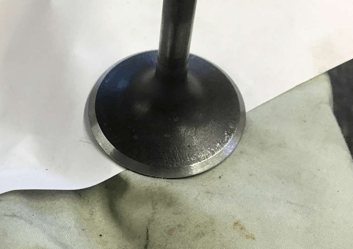
Some small dabs of fine lapping paste and a quick twirl of the lapping tool produced a nice even band around the valve, so it looks like I did get may angles right after all.
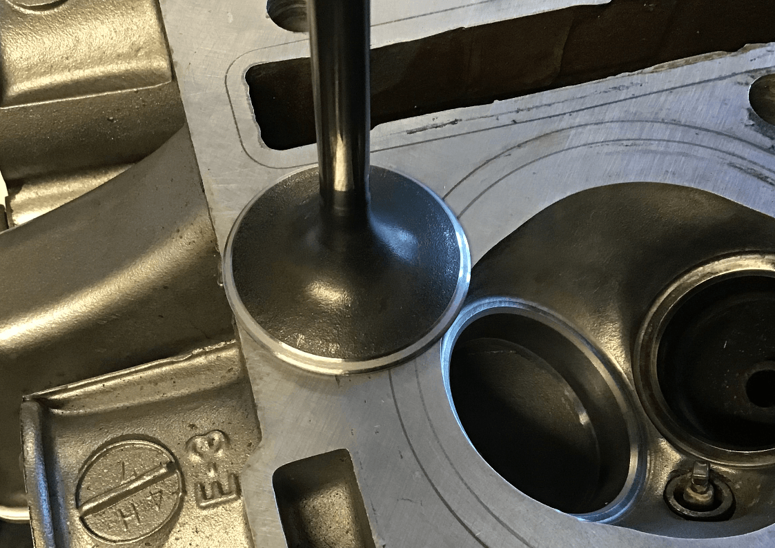
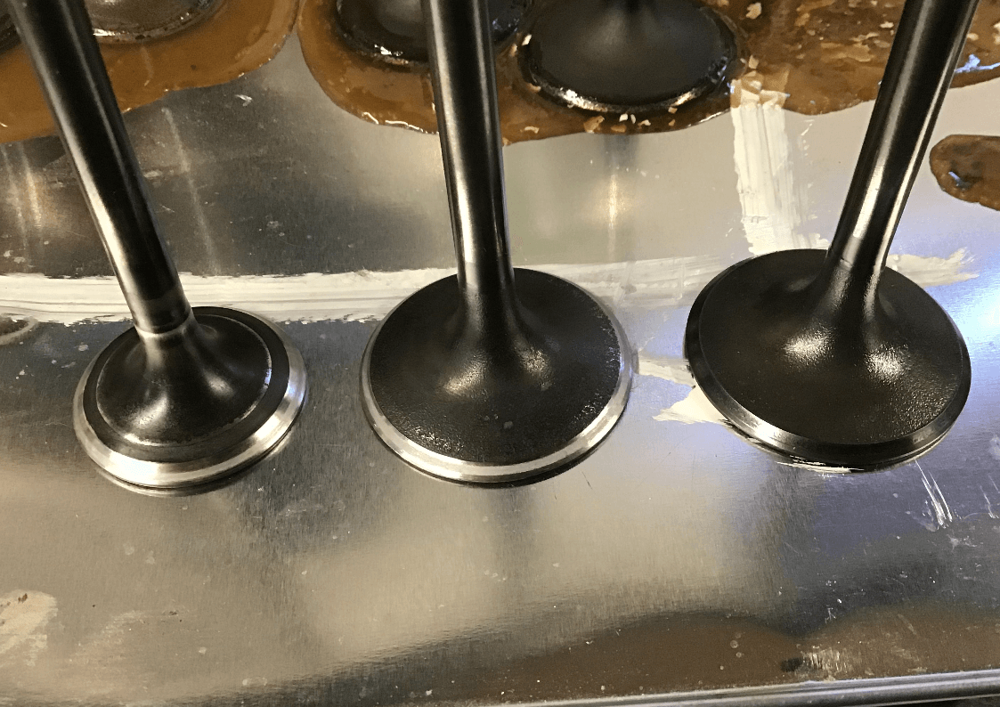
An exhaust and inlet valve after re-facing and lapping in, next to the inlet valve that’s next in line for the refacing treatment.
The complete refacing rig, complete with voluminous dust sheet.
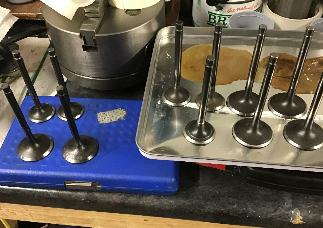
A row of shiny, refaced valves. Next job is to measure them up to make sure they meet the required factory tolerances, and then back in the cylinder head they can go. Now I need to go and clean the lathe down.