June 2018

In this last part about measuring tools in the workshop, we will look at micrometers and bore gauges. Now we’re getting to more specialist tools and you’re really only going to want this kind of stuff if you’re doing serious machining or engine building work and need really accurate readings. Otherwise, you can make do with a decent digital vernier.
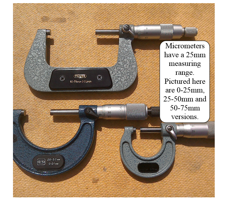
In the engineering world, if you want an accurate reading, you reach for a micrometer. The nature of the instrument allows more ‘feel’ than a vernier caliper. Basically with a vernier, you’re squeezing the jaws of the caliper onto the work piece. The screw action of a micrometer allows you to gently sneak up on the work, and you can feel when the micrometer is properly snuggled up to it! Most micrometers also have a ratchet mechanism which stops them from being over tightened.
There are several disadvantages though:
1) Digital versions are quite expensive, so you need to learn how to read a standard micrometer’s scale.
2) They only cover a 25mm range, so you may need several of them.
3) You need to make sure that they are calibrated before use. Each micrometer should come with a setting gauge and spanner to allow it to be adjusted. (The 0-25mm can be calibrated by closing the jaws fully and checking that it reads zero. Bigger micrometers will need to be checked against an accurate standard before use.) Despite that, you will see an abundance of micrometers in engineering workshops because of their accuracy and repeatability.
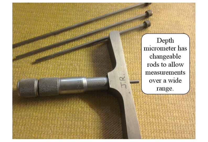
The picture (below) shows a variation on the micrometer theme. This one is a depth micrometer. Thankfully, unlike standard micrometers, these have interchangeable rods to allow a range of depths to be measured with one instrument.
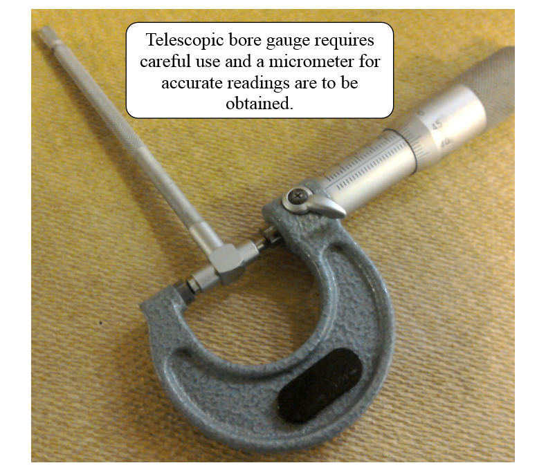
Finally, the last picture (below) shows a telescopic bore gauge. The ends of these are sprung loaded. To use it, you squish the ends together so that they just fit into the hole you want to measure. The ends are then locked in place by turning the knurled locking screw at the end of the handle. Unlock them once they’re in the hole, and give it a wiggle to make sure that everything’s centered. Carefully tighten up the lock nut and remove the gauge from the hole. Now select the appropriate micrometer and measure across the ends of the gauge.
Well that’s the end of a (brief) look at measuring in the workshop. There will be a more in depth article in the next issue (Issue 8) of the magazine. Including how to read those pesky micrometers. It’s worth reiterating that unless you’re going to start doing lots of fancy engine, machining or chassis work, all you’ll probably need are a rule, tape measure and a small digital vernier.

I know we ‘should’ always read the manual before starting a job on a bike, but sometimes we ‘think’ we know what we are doing - and so we plough on regardless, until things don’t turn out quite as we expect…
My error this time involved the fitting of new wheel bearings into the wheels of my project bike. The old bearings came out, and the new bearings went in fine. I even remembered to put the spacer back in. (Yes, I’ve done that before. Nothing deflates you more from the elation of successfully changing your wheel bearings, than to notice that the spacer that should be in the hub between the bearings, is still laying on the floor.) Wheels back on. Everything Ok. Or so I thought…
Fast forward a few months and as the bike is starting to near completion, I’m becoming more aware of its need to be able to pass the MSVA and MOT test. One of the things that I wanted to check was the wheel alignment. With the aid of two old fluorescent tubes to act as straight edges (knew I’d kept them for some reason) I started eyeing things up. Well, it soon became apparent that the wheels were not sharing a centre line. We’re not talking much here, a few mm, but enough that it really needed sorting - if possible.
Given that I’d made the rear wheel spacers, but the front used all OE equipment, I thought that this was perhaps the area that could have caused the error. Looking at the rear caliper, it was also obvious that the rear disc was not central to it. Could I have made the spacers incorrectly? But, then again, I didn’t remember there being a problem before I’d changed the wheel bearings. Surely, they couldn’t be installed incorrectly. Could they?
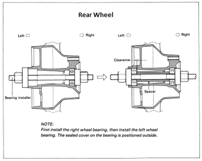
Now in my defence (just getting my excuses in now) I’m used to changing the wheel bearings on MX and trials bikes. In all of these that I’ve done, the bearings in each side of the wheel butt up to a shoulder in the hub (not forgetting the spacer!).
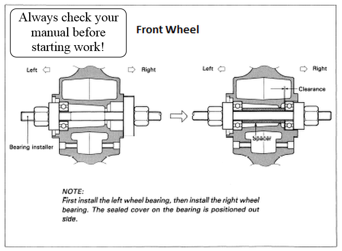
Turns out though, that for a Suzuki GS500, that’s not the case. Only one of the bearings butts up to a shoulder, and which one this is, is critical to getting your wheels in line; because for the front wheel, it’s the left wheel bearing, and for the rear, it’s the right. Now, if you follow the procedure as instructed in the manual, your wheels line up perfectly. So remember, always Read The Manual - ideally before you start the job!

In the second part of owning up to the times when I’ve engaged spanners before brain, we visit the electrical system, more specifically the charging circuit.
Ever since I bought my GS500, 3 ish years ago, I knew the battery was past its best. But given that this bike isn’t used often, I just used to plan ahead and make sure that the bike had spent some time plugged in to the battery optimiser before I needed to use it.This worked fine until just recently when even the battery charger couldn’t resuscitate it enough to turn the bike over. Time then to stop being a tight wad, and shell out for a new battery.
Battery purchased, filled with acid and stood as the instructions required, before fitting it to the bike and connecting the battery optimiser for a spell, to ensure that everything was tip-top. As the seat was off, and all the connections accessible, I decided to check out the charging system - just to make sure everything was Ok.
The bike started up fine. At idle, the voltage was in the high 13s, but as revs were increased, the voltage dropped to below 13V. This was not what I was expecting. I was anticipating that the voltage across the battery would be higher at 5000 rpm than at idle. I reached across for the Haynes manual, which specified that the voltage should be between 13.5 and 15.5V @ 5000rpm. As I wasn’t getting above 13V, I decided that something must be wrong, so I moved on to test the alternator output. The Haynes manual specified 75V at 5000rpm. Well I didn’t quite get 75V, but it was close enough for me to feel that all was well. As everything else was checking out Ok. I decided that the fault lay with the regulator/ rectifier.
Testing the rectifier is slightly complicated as the Haynes manual specifies resistance values measured using the genuine Suzuki pocket tester. If you try the tests using a digital multimeter, you won’t get these values - it doesn’t mean your reg/rec is faulty - you need to test it in a slightly different way. (There’s not space to detail this here. It will come up in the magazine in due course. If you want to find out how to do it now, I suggest you look up the Youtube channel of Electrex world.) Despite testing out Ok, I’d convinced myself that the reg / rec was causing the problem. The multimeter check can only check the rectifier diodes, it doesn’t really tell you anything about the regulator circuitry. After much deliberation (I don’t really like to part with money) I decided to stump up for a secondhand reg / rec.
I then hooked the bike up to the battery optimiser, and waited for the postman. Three days passed, and the reg / rec arrived. Out to the garage for a quick swap. Start up the bike, 14+V at idle, rev it up, oh no, voltage dropping again, but it manages to stick above the minimum 13.5V @ 5000rpm specified. Hmm, is this Ok or not? Now I’m starting to get confused. Time to spend some time with both the Haynes manual, the genuine Suzuki one and perhaps a bit of Googling.
Well, what did I learn? From the description of how the regulator / rectifier works in the Suzuki manual, it seems that at low revs (idle) the regulator part of the reg / rec is probably not actually functioning. (Extract from Suzuki manual shown below.)
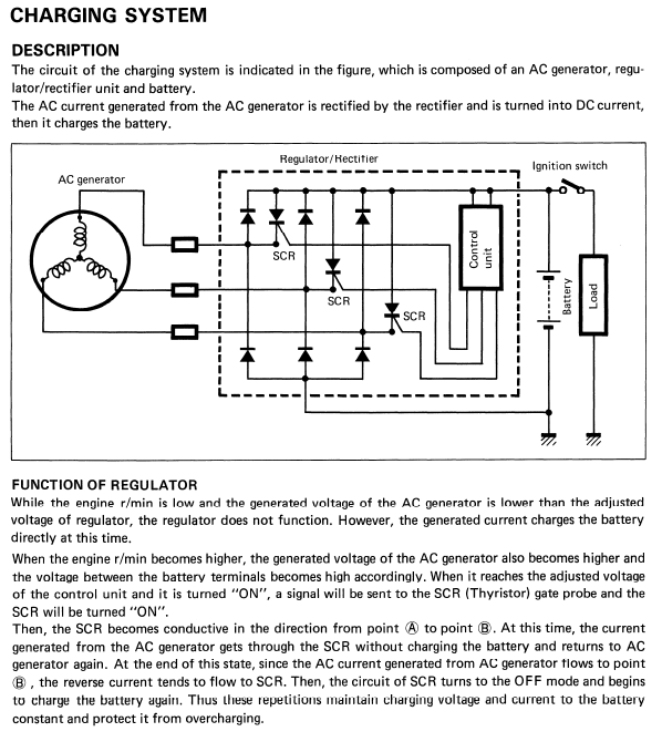
So the voltage output is just raw, rectified dc. No value is specified, but it is feasible that the multimeter may show a voltage reading greater than that achieved when the regulator circuitry kicks in at higher revs. Certainly, judging by posts on Suzuki based forums, I’m not the first to have experienced this. So it would seem that my charging system is in fact now working correctly.
So what of my original reg/ rec? Was it faulty? Well there was also another informative bit in the Suzuki manual. It’s shown below. In my eagerness to get things done, I don’t think that I had sufficiently charged the new battery before undertaking the test. So it may actually have been perfectly Ok. One day, I’ll swap the reg/recs over again and see.

For a really good link on rectifier / regulators and battery charging, try this:
For more on Regulator / Rectifier types and specifications, try:
