
Monday Articles - October 2020
Back to the much more difficult (for me) job of bashing sheet steel into pretty shapes. I think my original fuel tank design may need to be simplified to cope with my lack of skill. I'm trying to reduce the number of different radii used to just two or three, rather than the multiple complex curves and radii that the foam and resin pattern has. Hopefully it'll still look OK. If it doesn't, I can have another go, and if I really can't get the job done in steel, I can always turn to plan B and have a go at a fibreglass version.
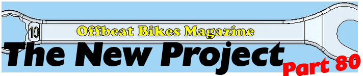
These are some freshly turned dollies, whose various diameters and radii will (with a little luck) help me fashion the petrol tank.
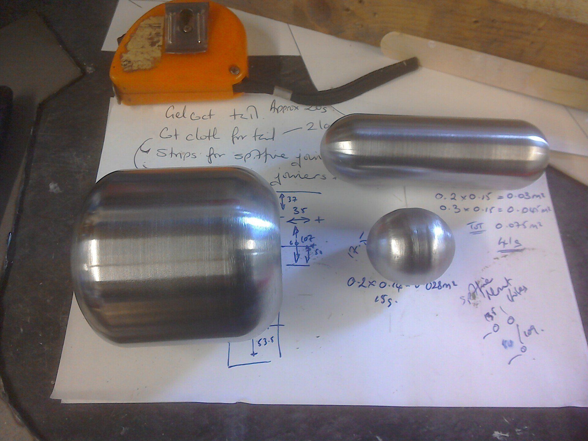
The dollies have grown some tails so that they can be firmly clamped in a vice whilst I hammer sheet steel over them.
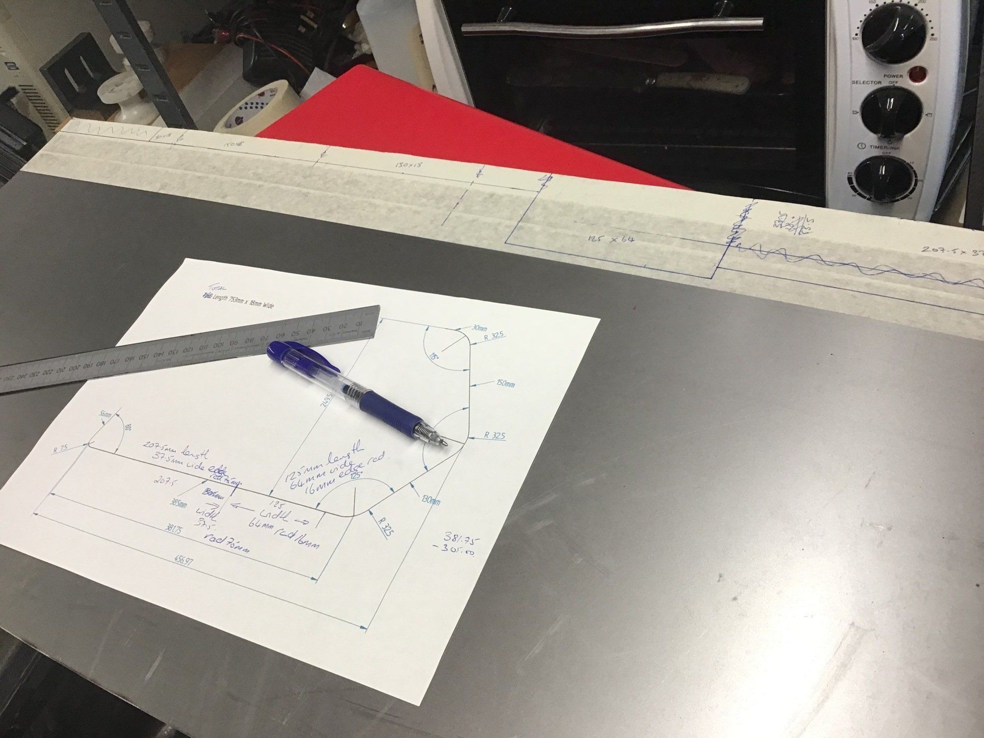
I've also been rethinking how to section parts of the tank for easier reproduction. Depending on where I put the joins, parts could either be made from lots of pieces, each with a simple curve (curves in one direction only) or from fewer pieces with (harder to reproduce) complex curves (curves in more than one direction) - all of the while bearing in mind that the more welded seams that are required, the more opportunity there is for leaks!
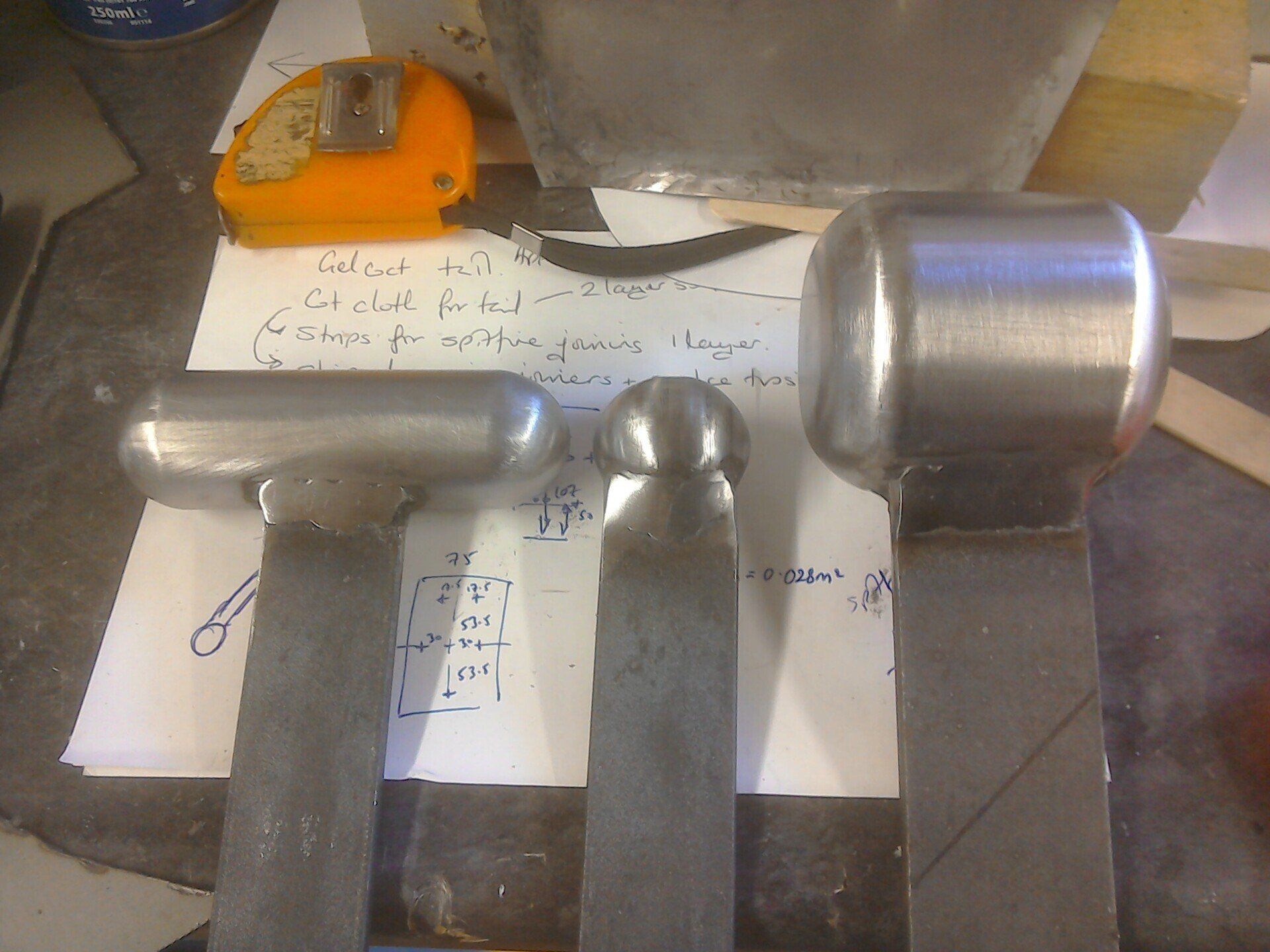
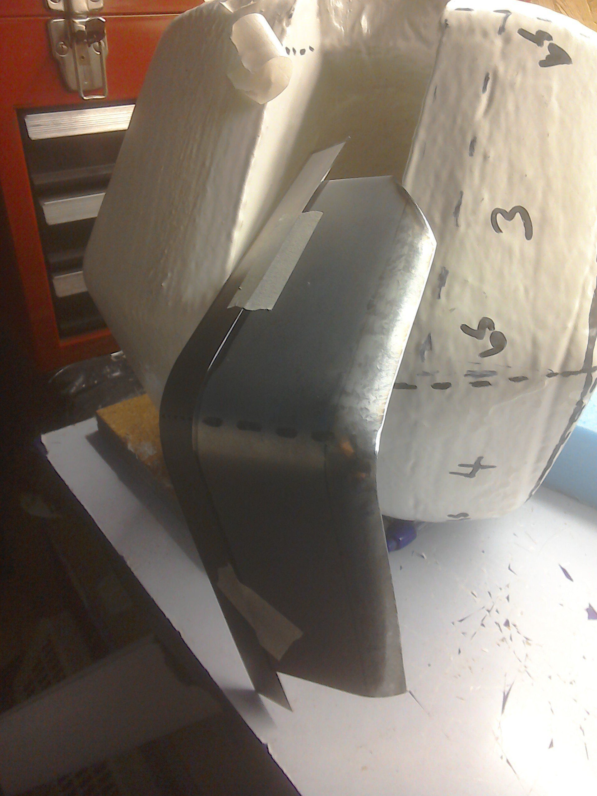
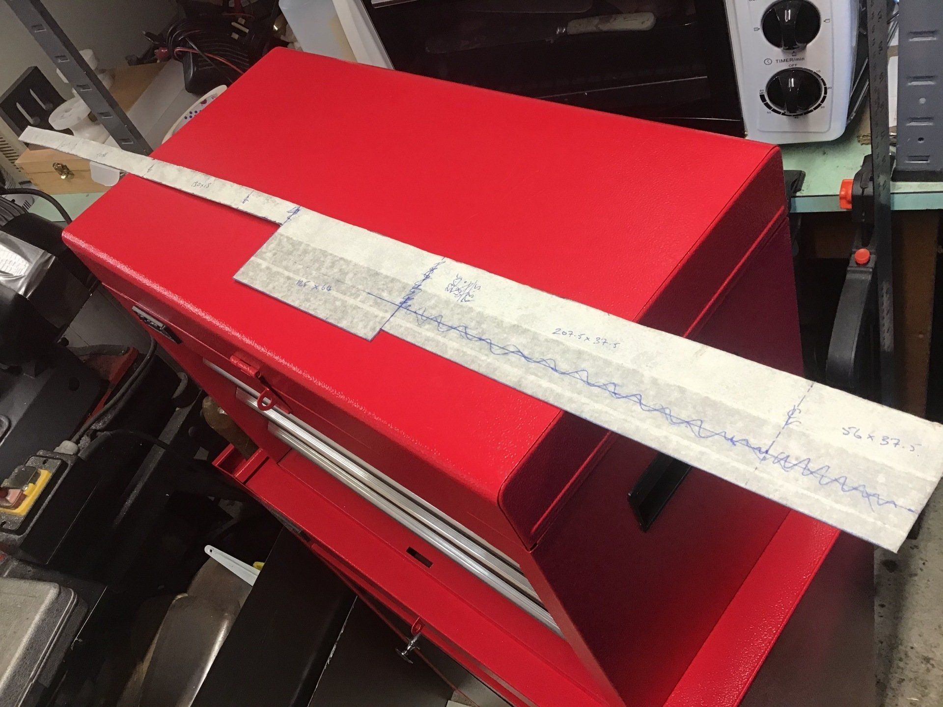
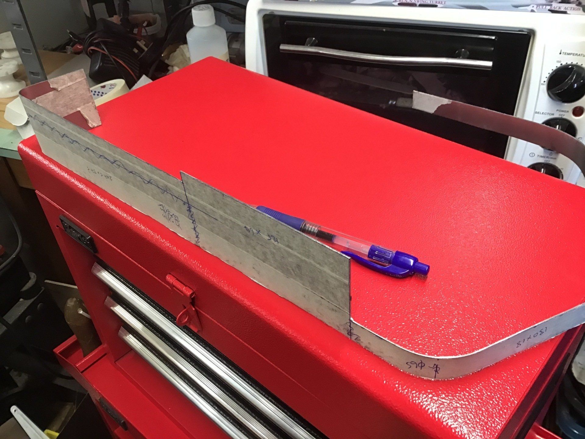
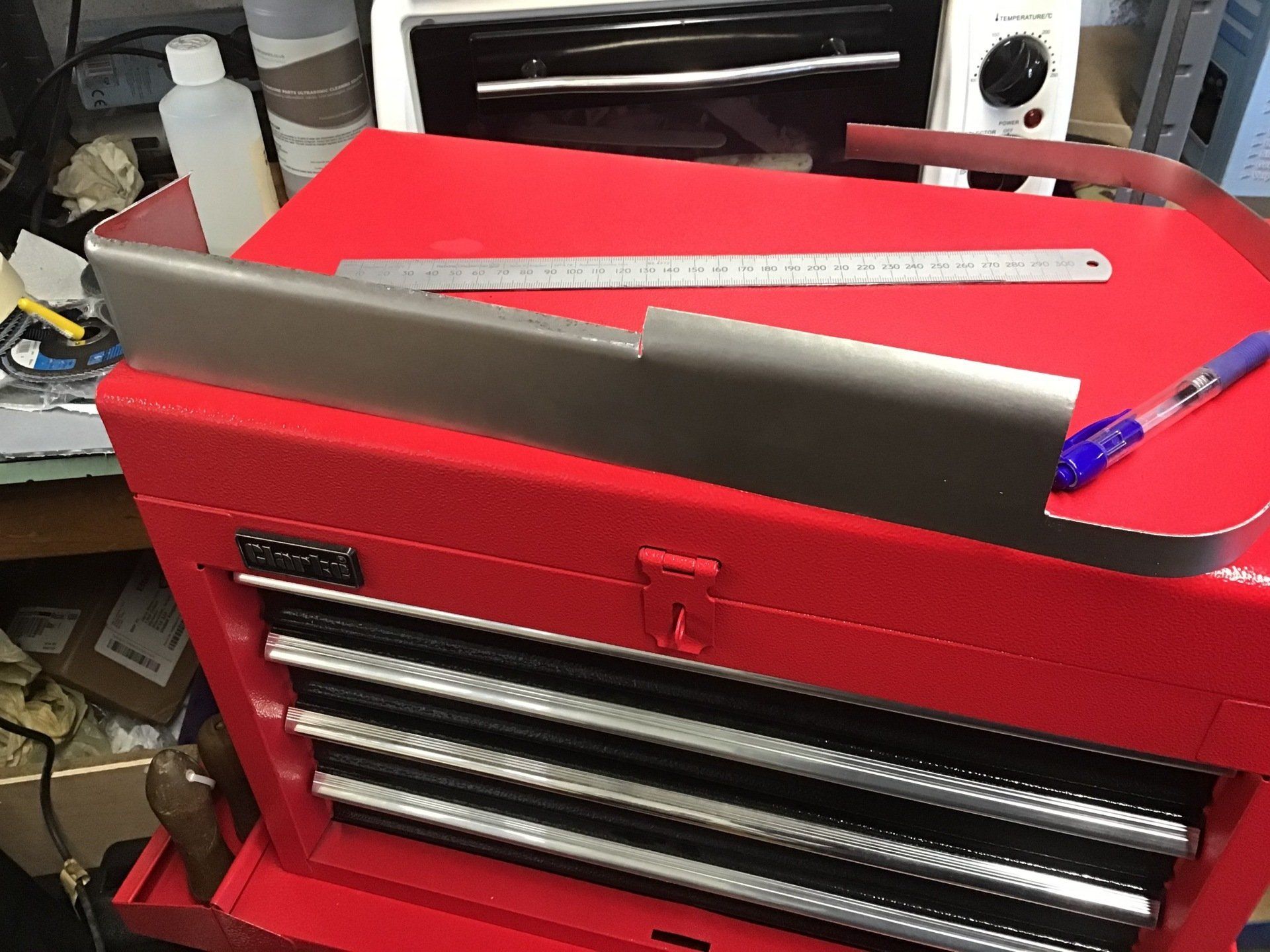
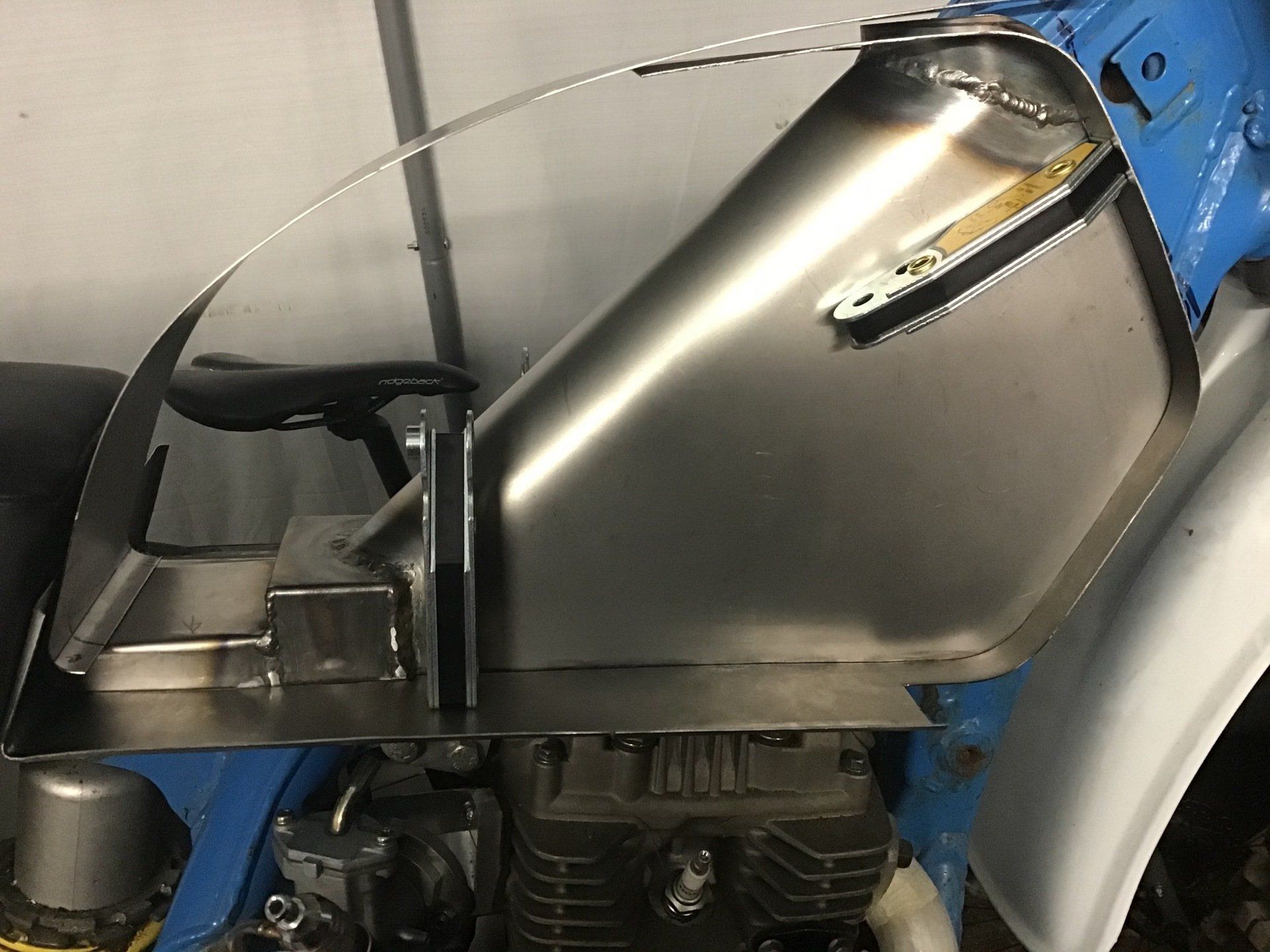
In the photo below, I've split sections 3 & 4 into a straight inner edge (about 20mm wide) with a simple bend in the middle and a separate outer section, which will have a bend in the middle and a radiused outer edge.
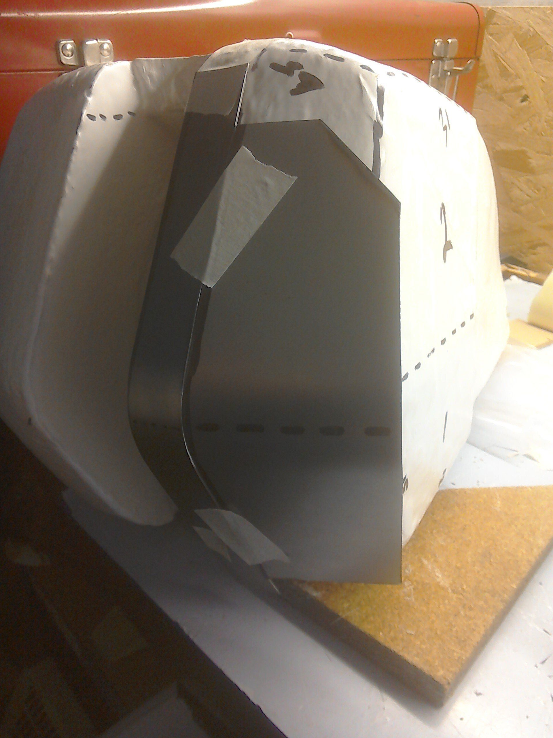
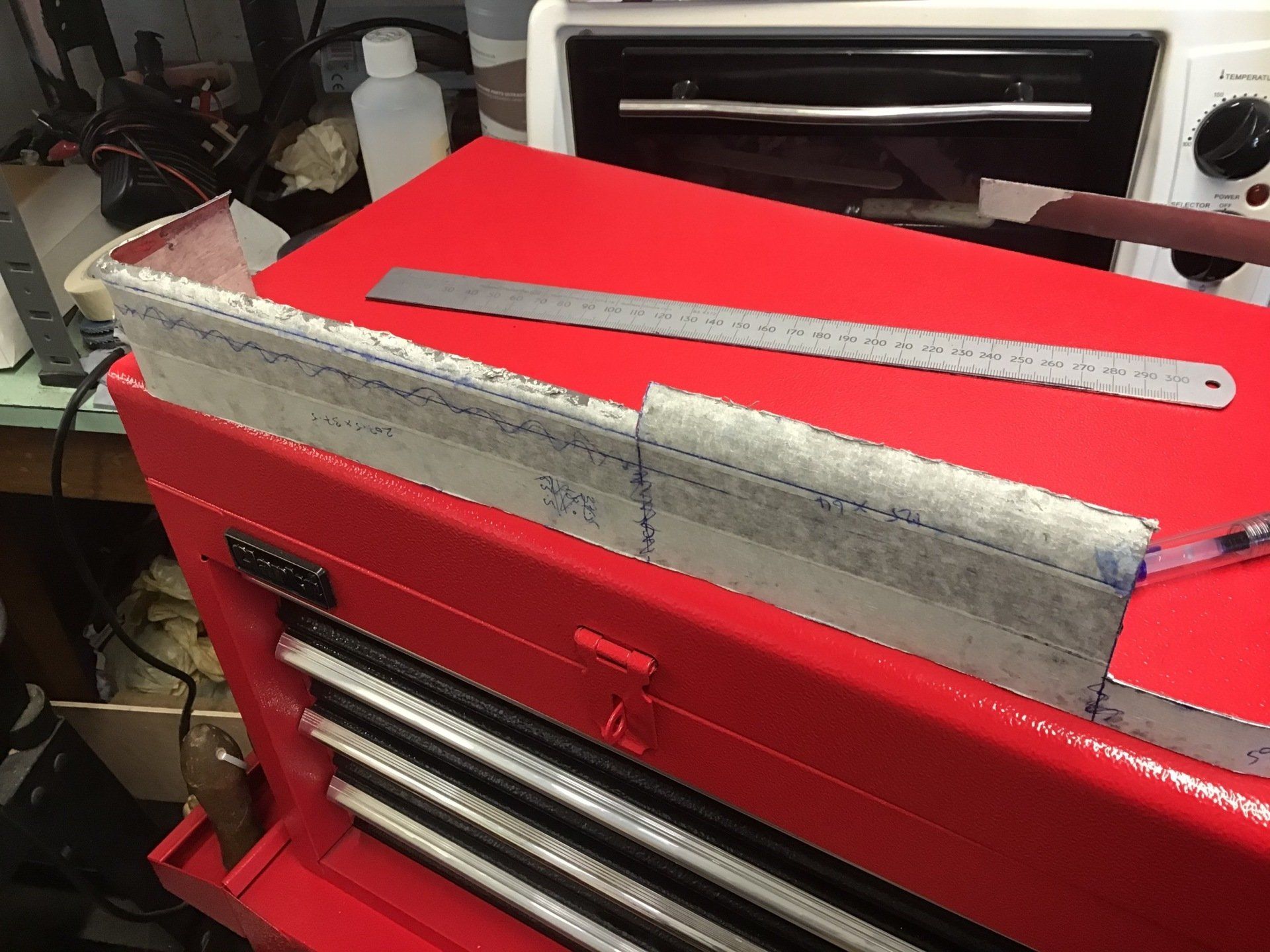
Here are the same two pieces again after the outer section has been attacked with hammer and dolly. It's looking promising...
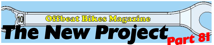
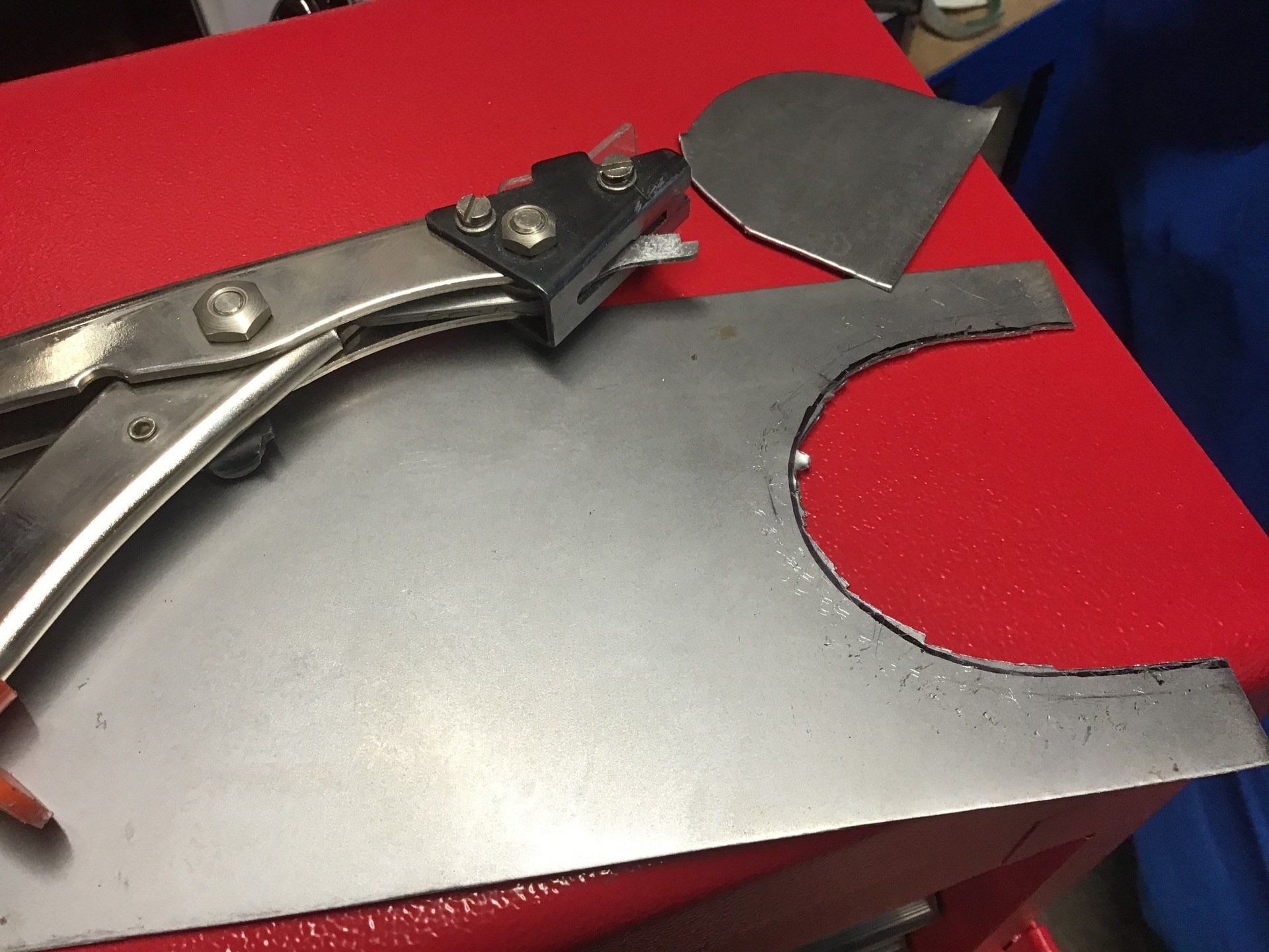
Equipment issues have slowed progress this week. First off was cutting out this semi-circular notch. Usually I cut sheet steel using either a small bench shear (good for straight cuts) or with a 1mm thick cutting disc in the angle grinder. Unfortunately, neither of these would cut out the notch required. Then I remembered that I owned a hand operated nibbler. As the name suggests, this cuts sheet steel by removing little 'nibbles' of metal. It's also hard work to use (well mine is) especially if you want to cut steel. This is only 1mm thick steel and the nibbler is capable of cutting 1.2mm so it should be able to handle it, and it does, in a fashion, but it gives the hand and forearm a good workout.

Here's the nibbler. This is an EDMA version, which I bought some years ago. Versions are now available from Sealey, Draper, Silverline etc. and vary in price from £12 to £30. Frost Automotive do the Eastwood version, but that's north of £70, so a bit pricey. For that money you could get an air or electric powered version.
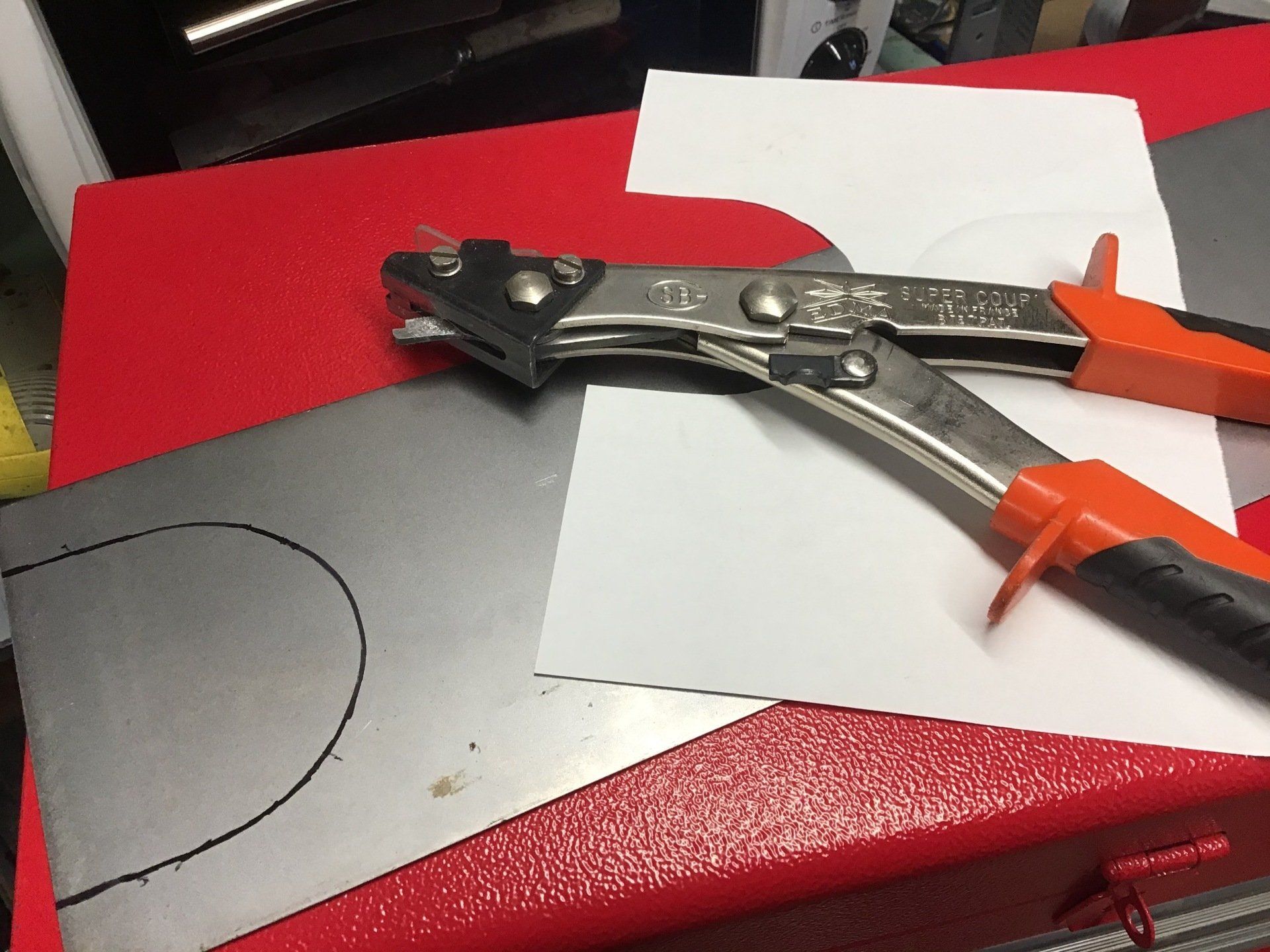
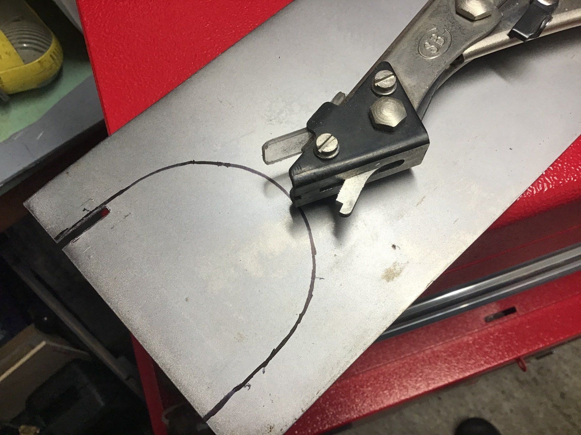
The job, after a few nibbles have been removed. I've probably already got arm-pump!
But, eventually, the job is done. I tidied the edges up using a carbide burr in a cheap electric rotary tool. (It's a Netta branded one that I bought via Amazon. Although Netta still exist, they no longer seem to be selling the rotary tool, concentrating on kitchen goods now. Perhaps it's just as well, although mine still works, the speed sometimes fluctuates and I feel that it may not be too long before the speed control circuitry packs up!)
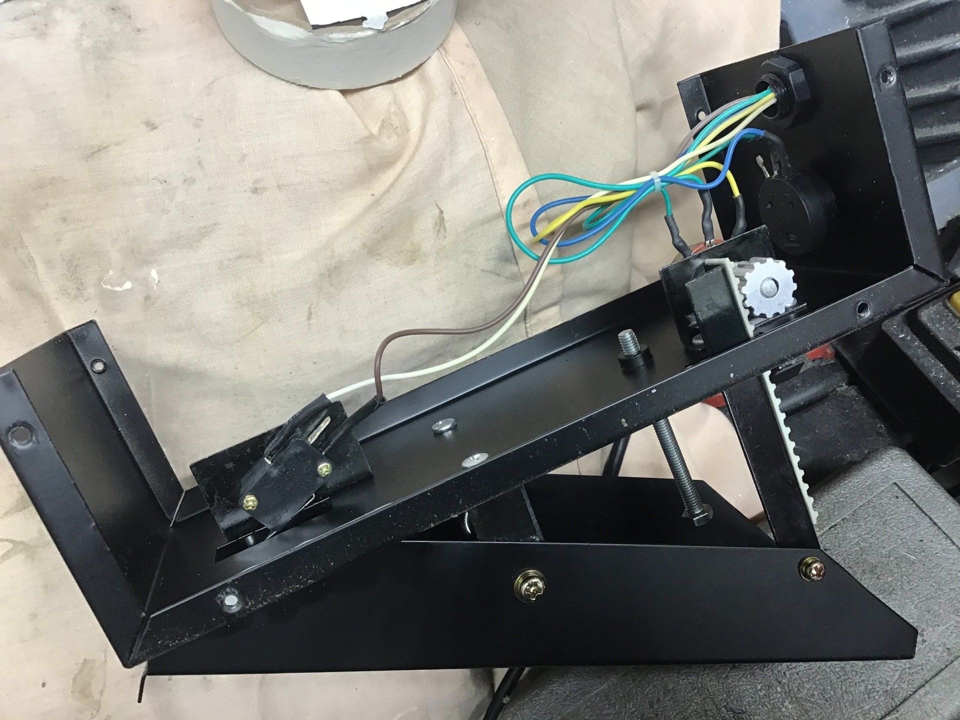
The next equipment issue was with the foot pedal for the TIG welder. I'll start by saying that both the TIG machine itself and the pedal are Stahlwerk branded items, so they should work together without issue. My problem is that this is thin steel and I want to turn the TIG amperage down low. Using the on/off switch on the torch and with the controls on the machine set to minimum, the output is really low. But, when I use the foot pedal, even with all variable settings set as low as possible, it is obvious that the output amperage is higher - I know this because with torch alone, it takes a while for me to burn a hole in the steel, with the foot pedal it's almost instantaneous!
After lots of faffing around with settings, I decide to take the foot pedal apart. It's a fairly simple two potentiometer affair and from what I can work out, the TIG unit provides a voltage to the foot pedal and the pedal feeds back a portion of this voltage depending on the position that the two potentiometers are in. This voltage must then be used by the internal circuitry of the TIG unit to determine the output sent to the torch.
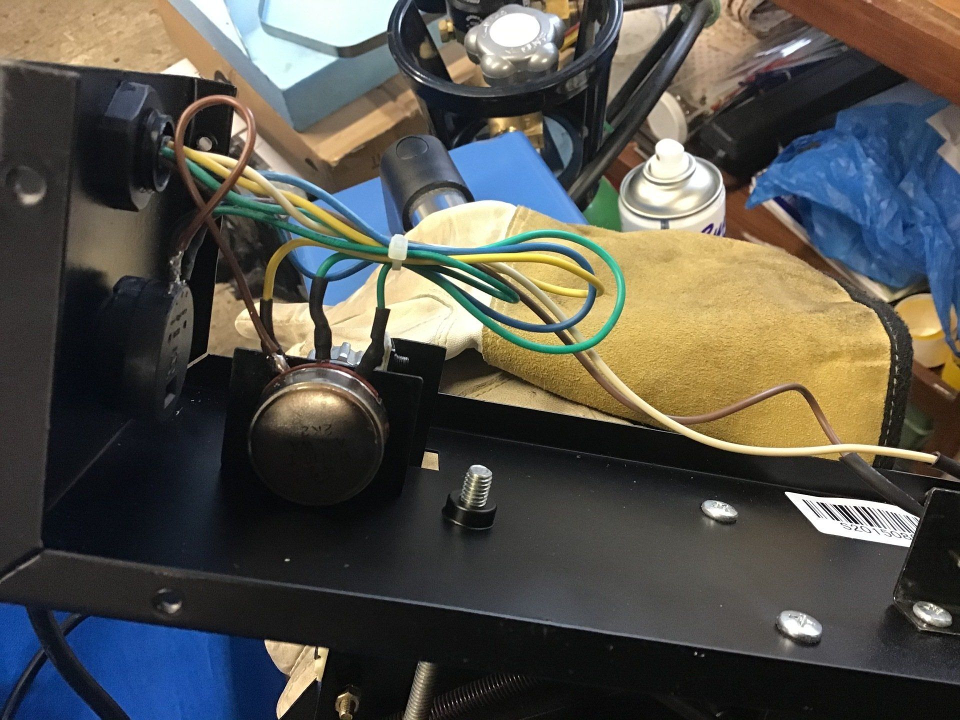
The only thing that I could see that might cause an issue is that one of the pots only has two connections used. It's wired as a variable resistor rather than a pot. As such it means that the voltage fed back to the TIG's control circuit will always be at some small value above 0 volts - could this be the problem?
To test out this theory, I added a wire from the unused terminal of the first pot to 0V (gnd). This does at least mean that with all of the pots set to minimum, the output will now fall to 0. (It's the brown wire, with the twist in the picture.)
Has it made any difference? I think it has, but the output from the torch still feels 'hotter' using the foot-switch than it does using just the torch switch.
If it's any use to anyone, the connections are as follows:-
Blue +V (from the TIG unit)
Yellow 0V
Smaller dia green wire - output from front panel control, input to foot pedal pot
Larger dia green wire - output voltage fed back to TIG unit
White and brown are for the ON/OFF micro switch, just out of picture on the right.
(Extra brown wire between pots added by me.)
Back to actually trying to make something this week. After looking at the dummy tank (endlessly, in an attempt to figure out how to actually build the thing) some sections are almost flat, with just simple curves to reproduce - so I decided to start there.
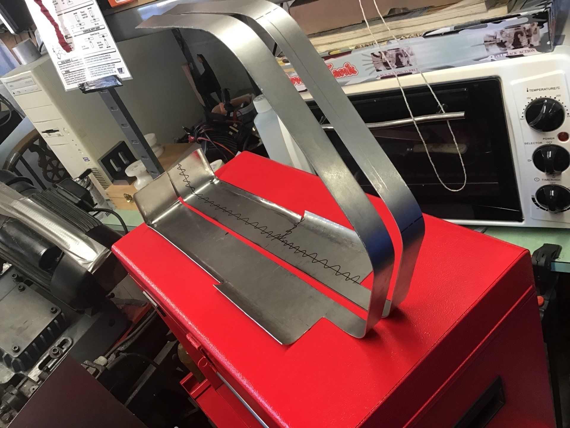
There's a strip (110mm wide to be precise!) along the top of the tank which on the dummy tank is almost flat across its width. For the steel tank it will be flat! This is the bit that I decided to attempt first. It was also the bit that needed that semi-circular notch cutting (see part 81).
The curvature required was formed by hand using shin bone and knee as the former. Given the rudimentary equipment that was used, it didn't come out too bad.
First trial fit on the bike reveals that the front notch needs to move back further. The excess at the rear can (for the moment) be folded under.

That's better, front has been trimmed to fit, rear folded to sit on top of tunnel at the back.
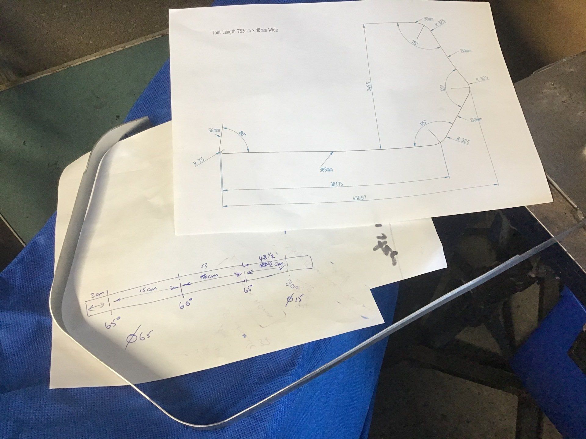
There's a strip (18mm wide) that is also flat across its width that runs around the rest of the tank, next to the tunnel. The original pen sketch is transformed into CAD drawing and the eventually into metal.
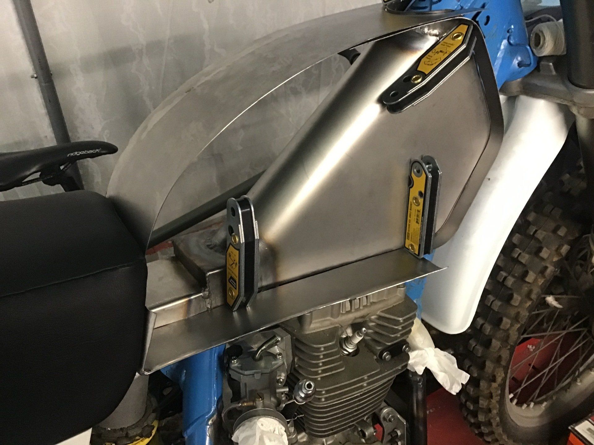
A trial fit (using some magnets to hold it in place) looks OK.
With the two parts temporarily in place, the basic outline of the tank can be seen.
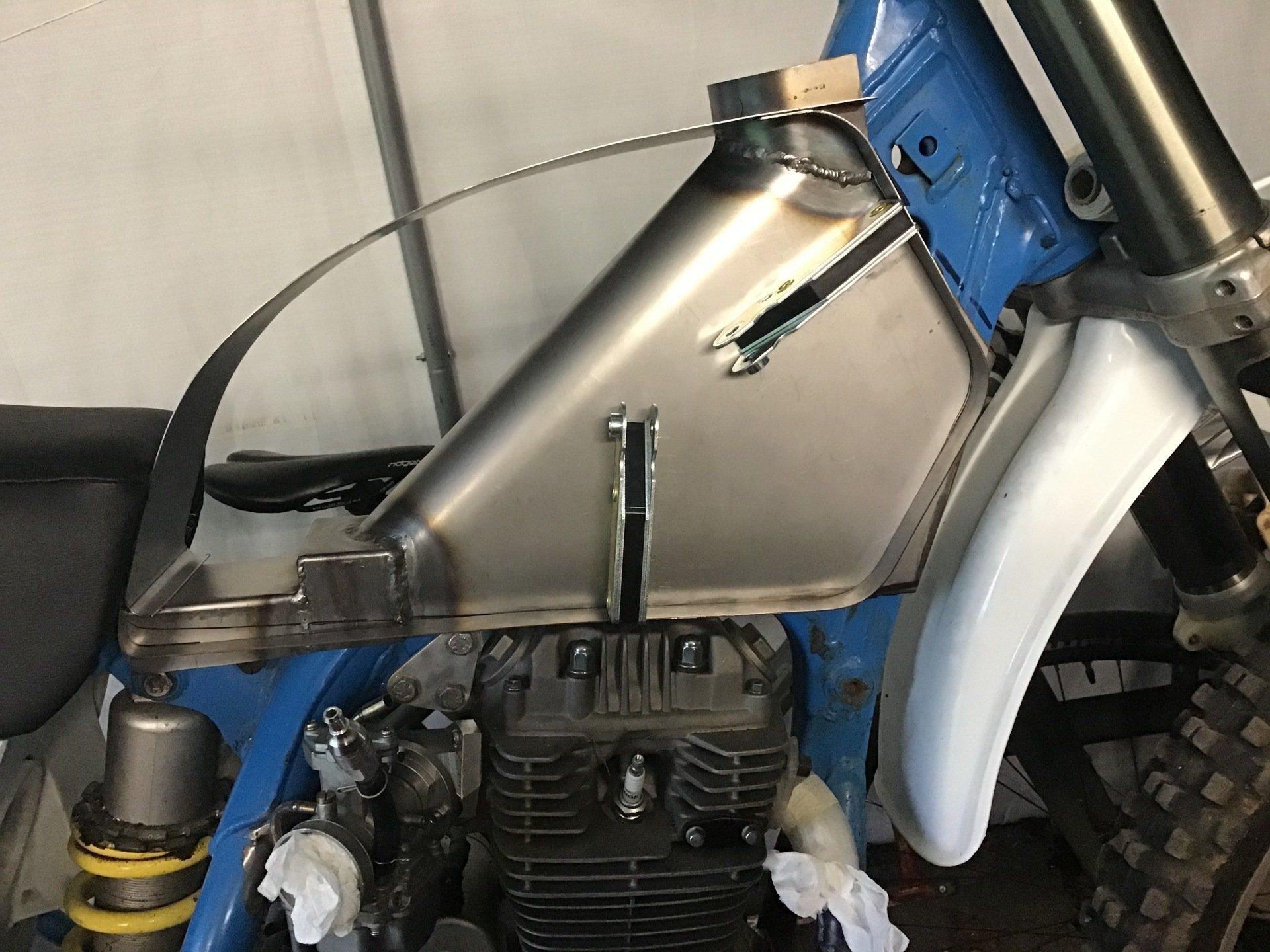
Tunnel has now been trimmed to match - so I hope I don't change my mind.
A little progress, then. It is all helping me to visualise how I might (eventually) manage to fabricate the tank. But, as I try to make bits, I come up with different (maybe better, who knows!) ideas, so don't be surprised if next week I've thrown this lot away and gone down a slightly different route...
If you’ve been following this project on the website, you’ll have seen the comment that I made last week. It was something along the lines of - don’t be surprised if by next week I’ve thrown this lot away and gone down a completely different route. Well, I haven’t thrown it all away, just had a change of plan...
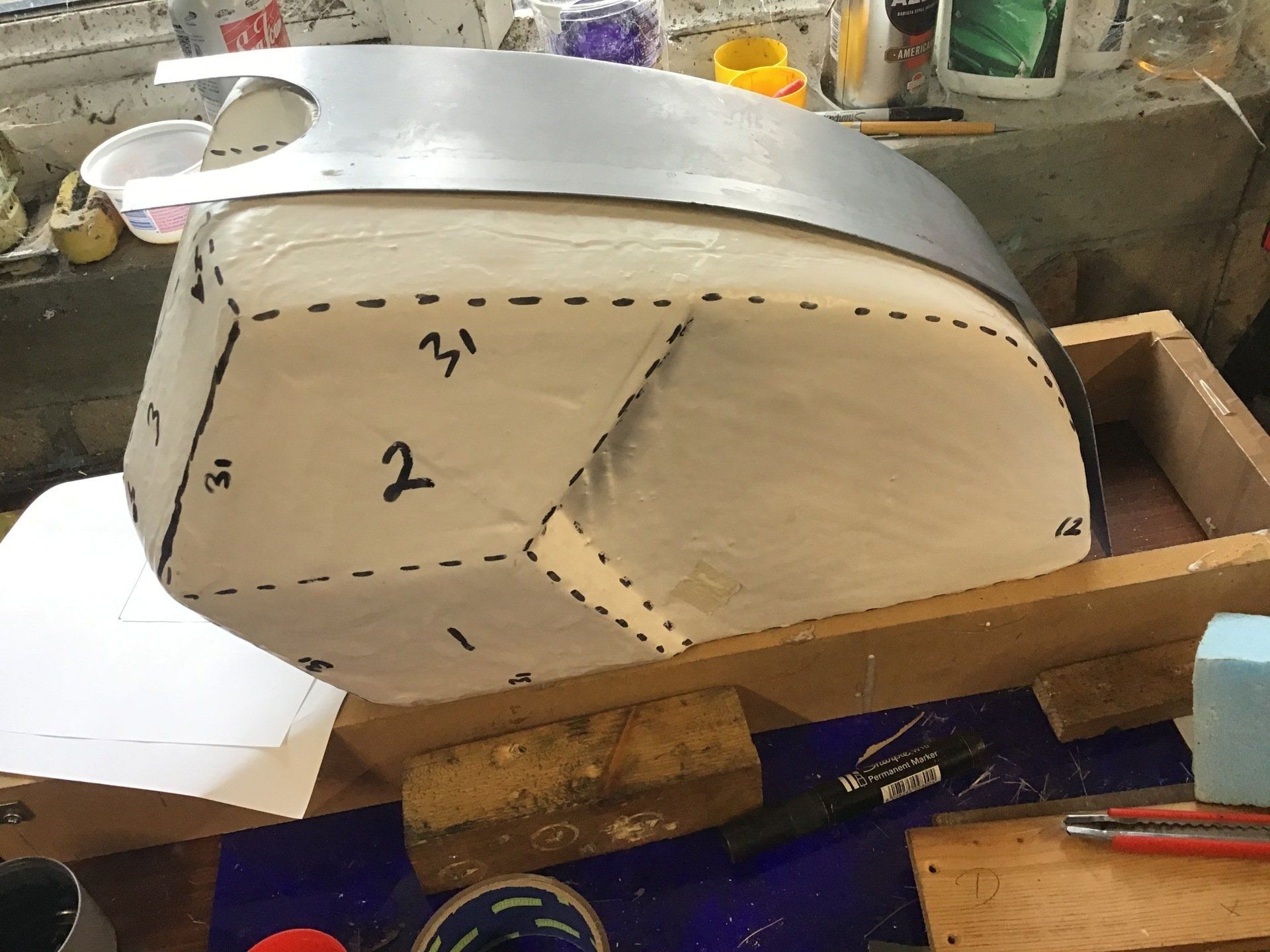
The underneath of the tank is largely flat, so why not extend the tank inner edge that I’d made previously to incorporate the tank bottom as well? And so, that is what I have spent this week doing. The photo below shows the bottom of the dummy tank and the original inner edge that I’d made. (Although this inner edge is actually sitting on the wrong side of the dummy tank!) The various scribbles on tank and strip are the new dimensions required.
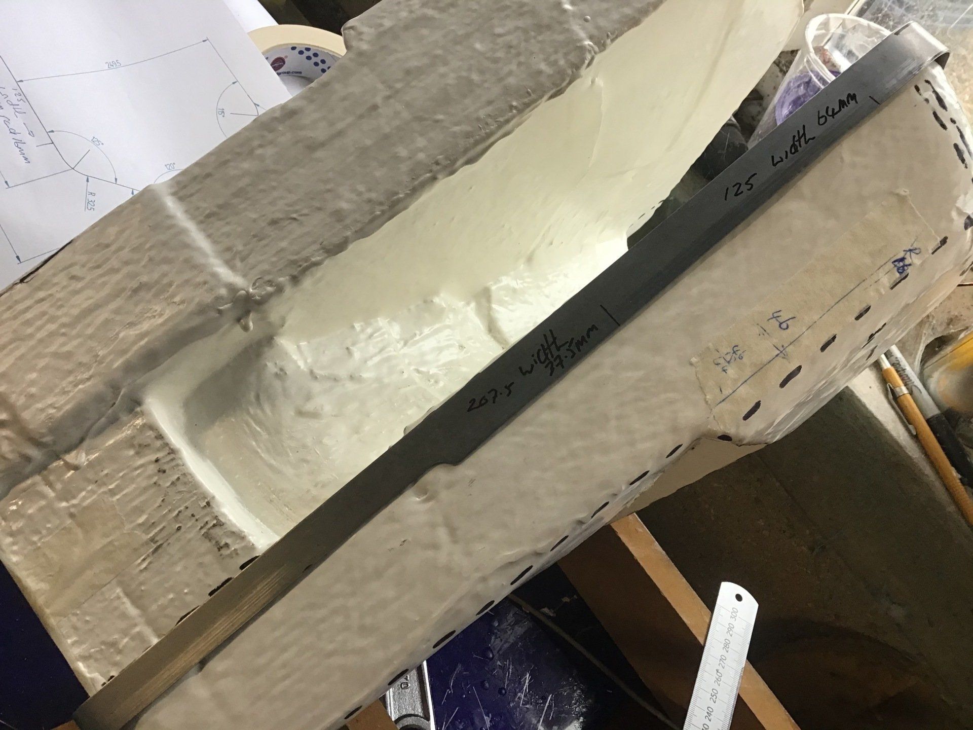
The required dimensions were then transferred to the sheet steel – although not without error. Thankfully I picked up the errors before I cut it out!
A combination of cutting disc, flap disc and hand file were employed to cut it out and tidy the edges.
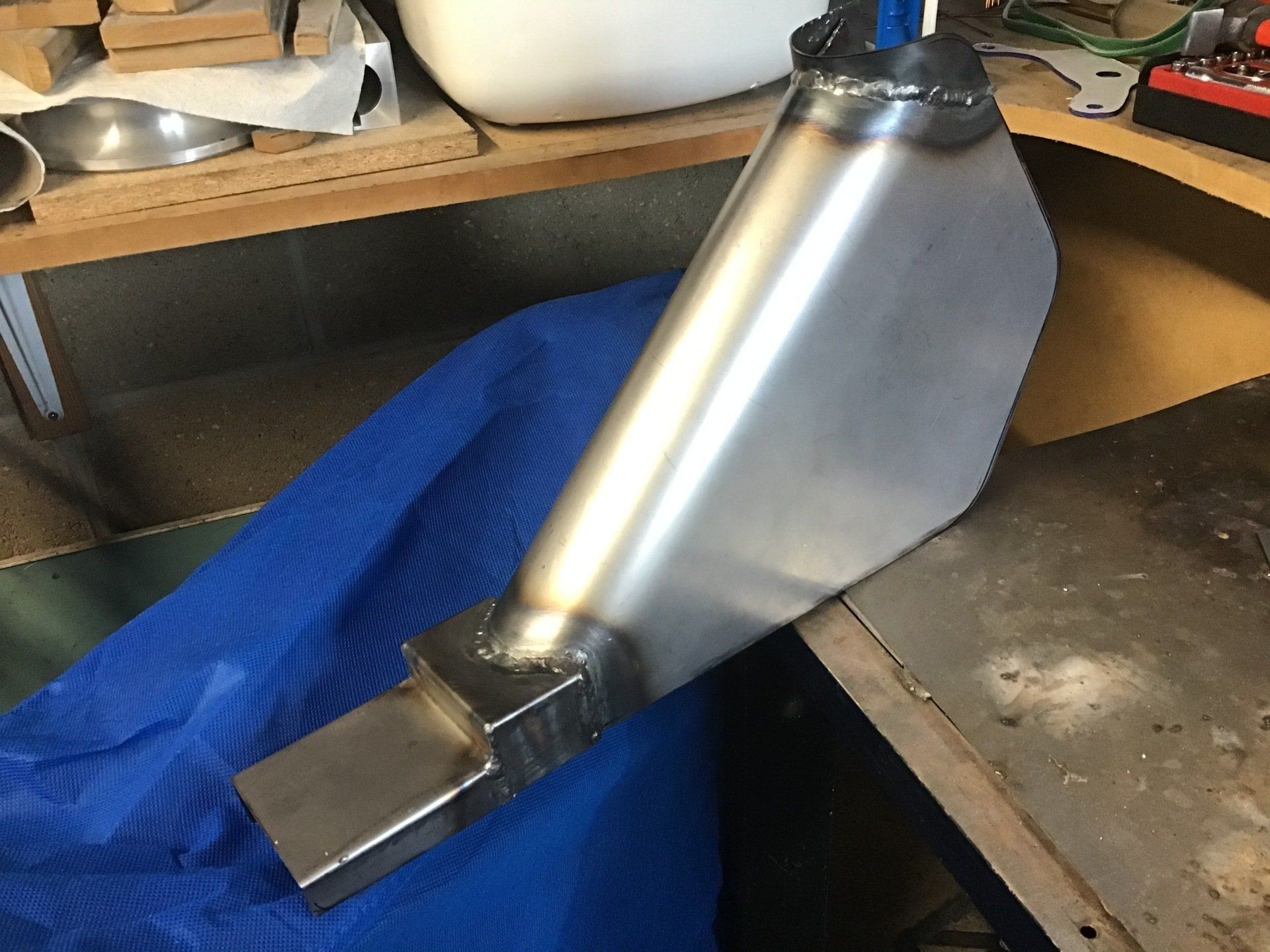
Then it needed to be bent to shape. This was done by hand, using the largest of my hand made dollies as the former for the front three curves, and a 15mm steel bar for the rear. I have a supersized protractor that I use to measure the angles.
The radii around the edges were then formed using a hammer and dolly as required.
...And with the masking tape removed.
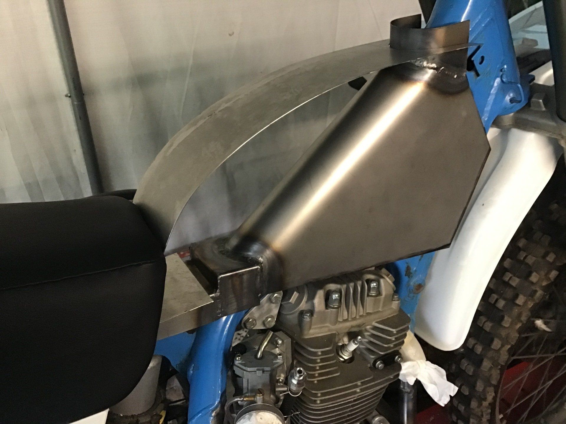
Time, then to offer it up. It looks OK. To be honest, at the moment I don’t know how it’s all going to work at the seat end, but that’s a problem I’ll ignore for the moment. It’s just one of many problems! The next one of which is to now make a left-handed version for the other side.
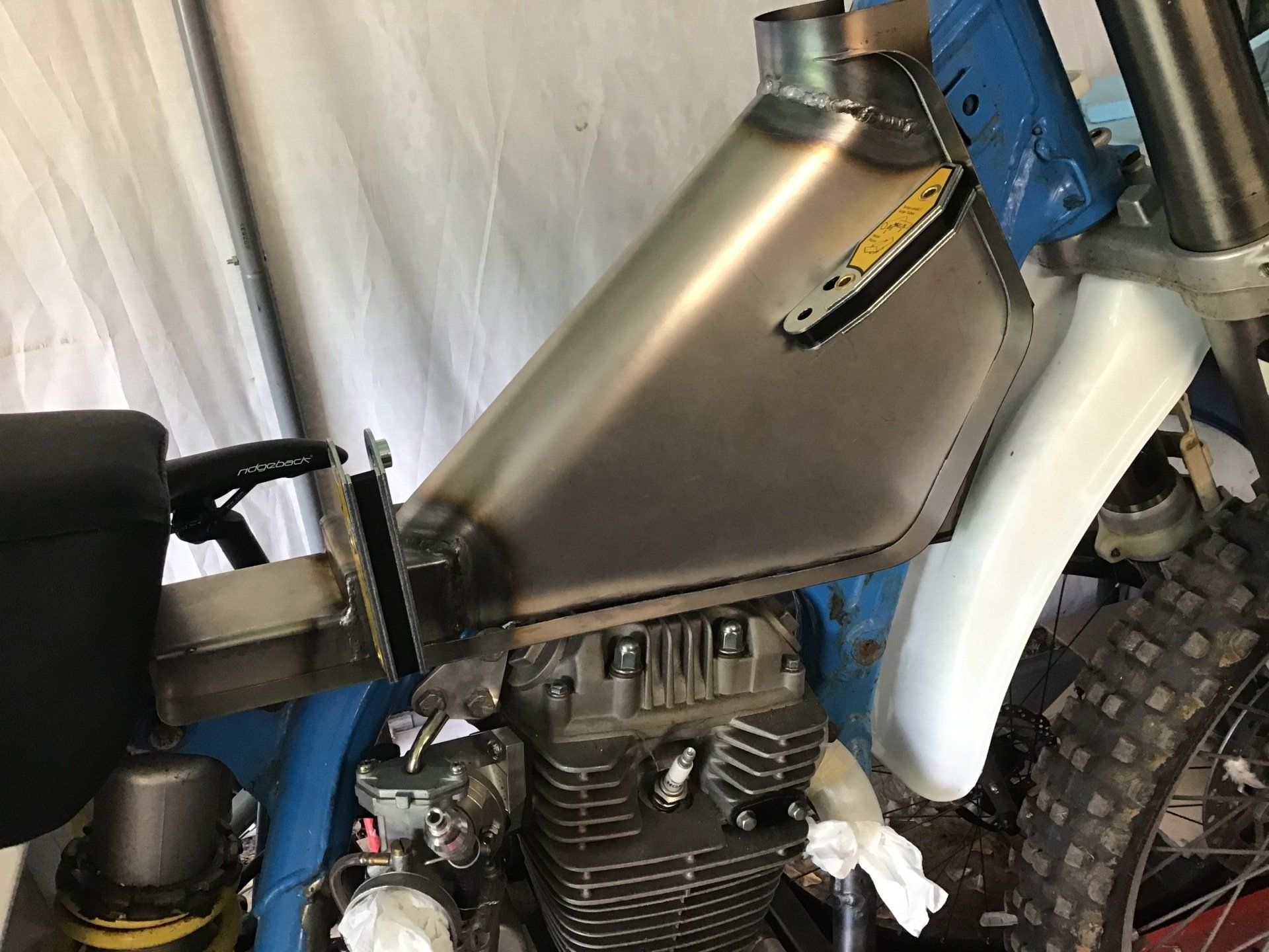
Second one actually turned out better than the first and I made my life easier by investing in a new marker pen - so that I can now write directly onto the steel, rather than having to cover it in masking tape so that I could use a biro.
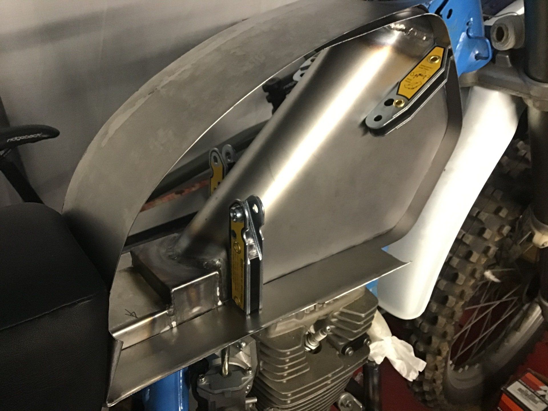
Here both sides are in place, although you can’t actually see much of the other side, sorry.
A slight change of plan, then, not for the first time and very probably not for the last time! Let's see what next week brings...