
SEPTEMBER 2019
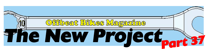
This week I have been trying to achieve what the note in the picture below asked for!
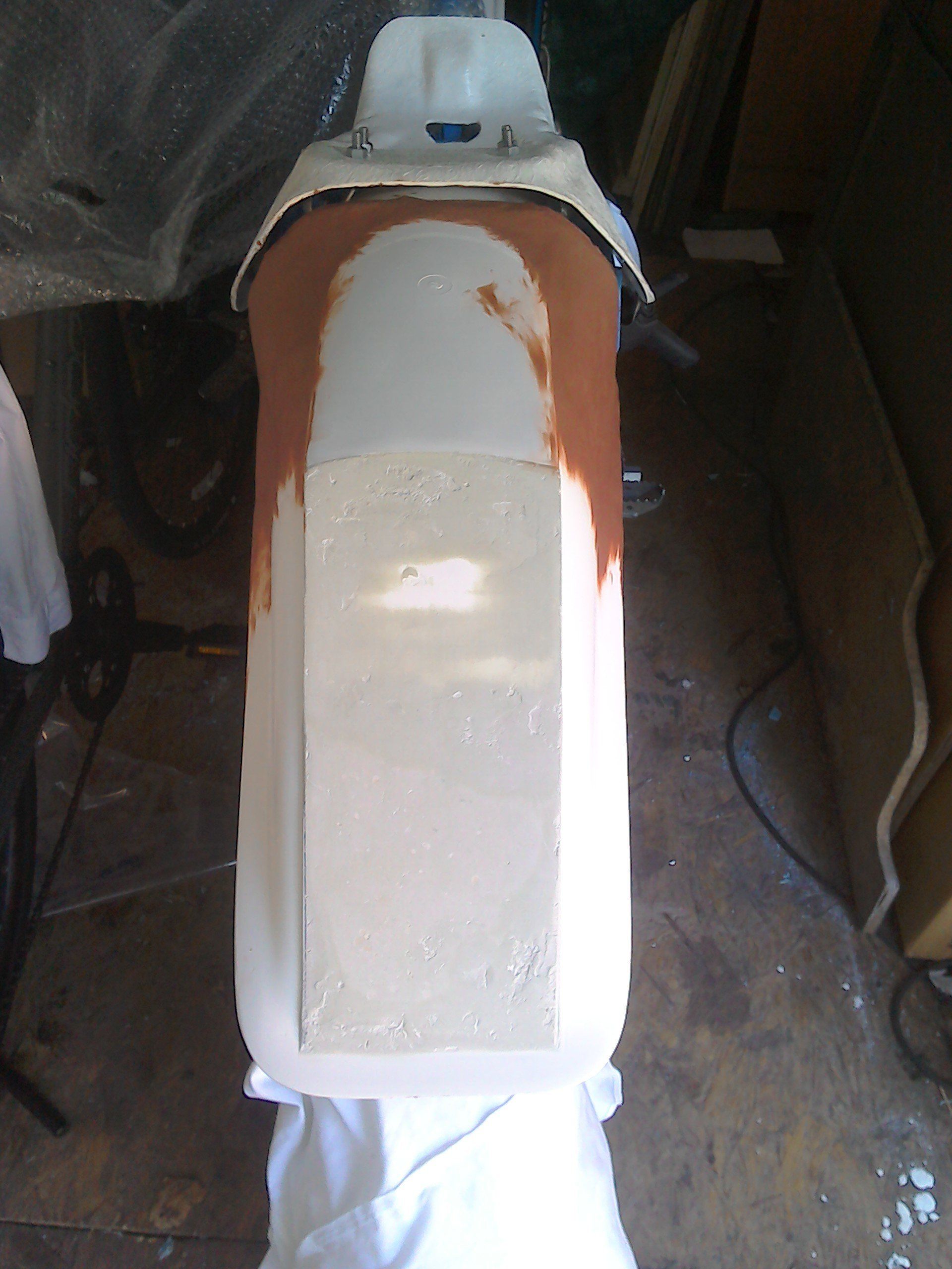
Yup, those frame rails and the join between the 'two' mudguards need hiding.
And with the help of some Chavant modelling clay, that's what I've been trying to do.
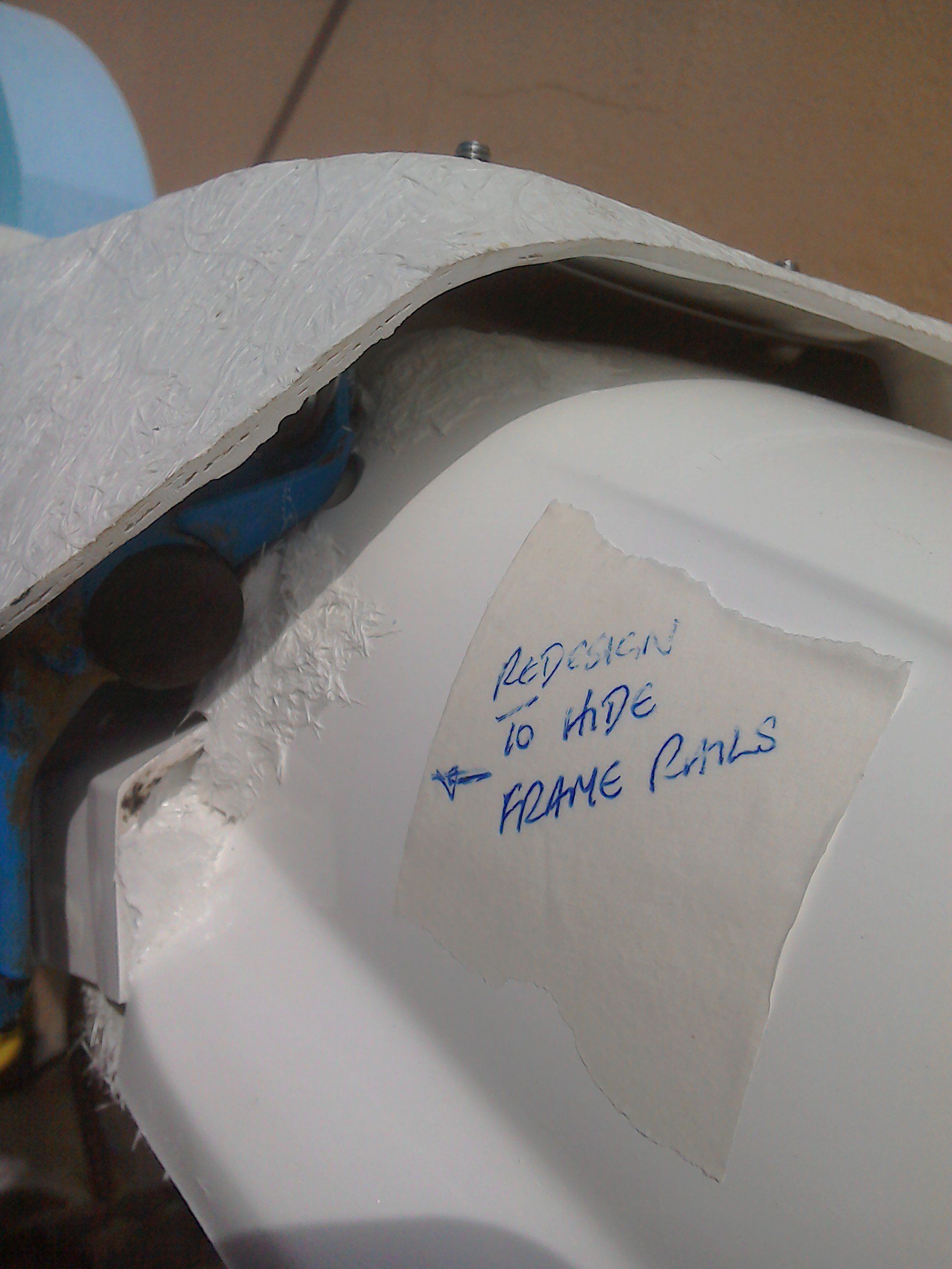
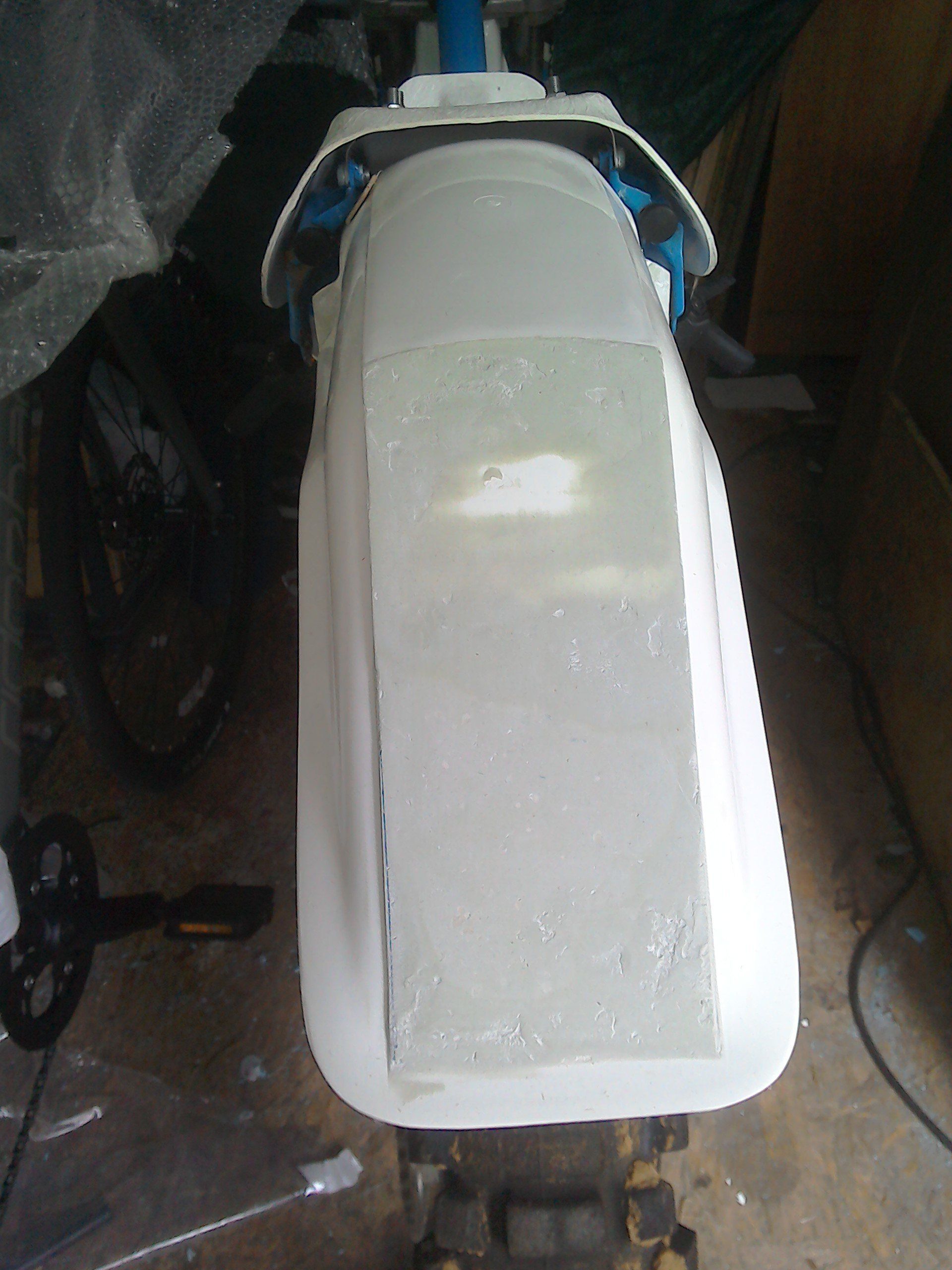
Modelling one side isn't so bad, trying to get the other to match is harder, but we're getting there.
This is the rear light fitting that I hope to use. Unfortunately to get it to sit so that the light is horizontal would either require a 'lump' to be added to the mudguard, or the light needed a new mount.
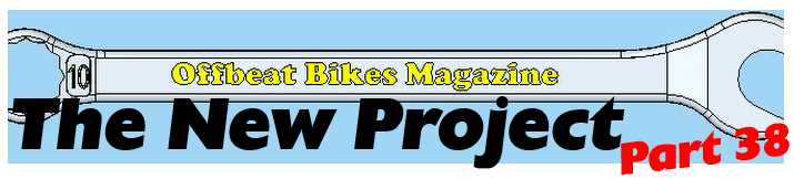
The lump on the mudguard looked pretty ugly, so the light was reduced to its component parts...
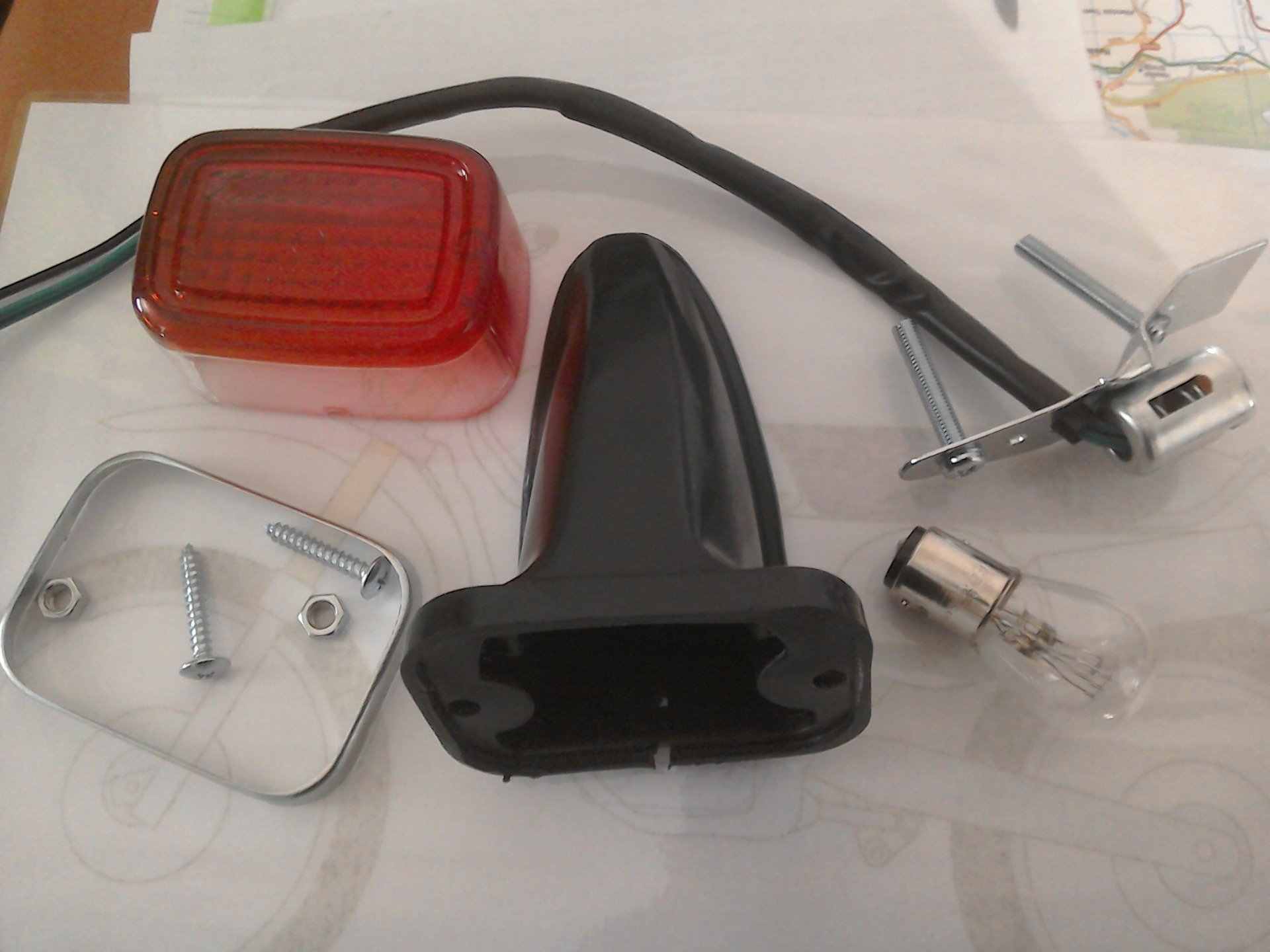
... and a new mount designed.

The 3D printer is busy printing it out. Next week, you'll (hopefully) see how I got on...
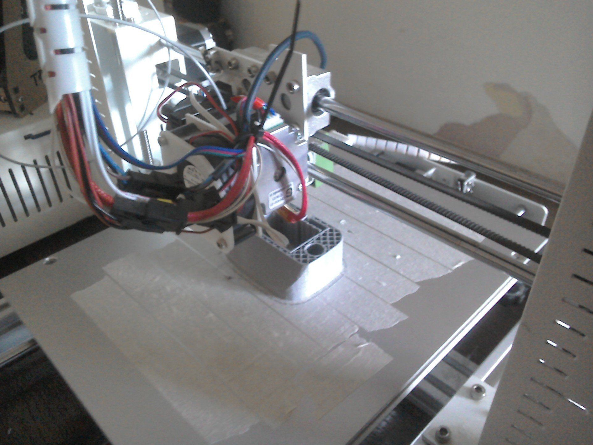
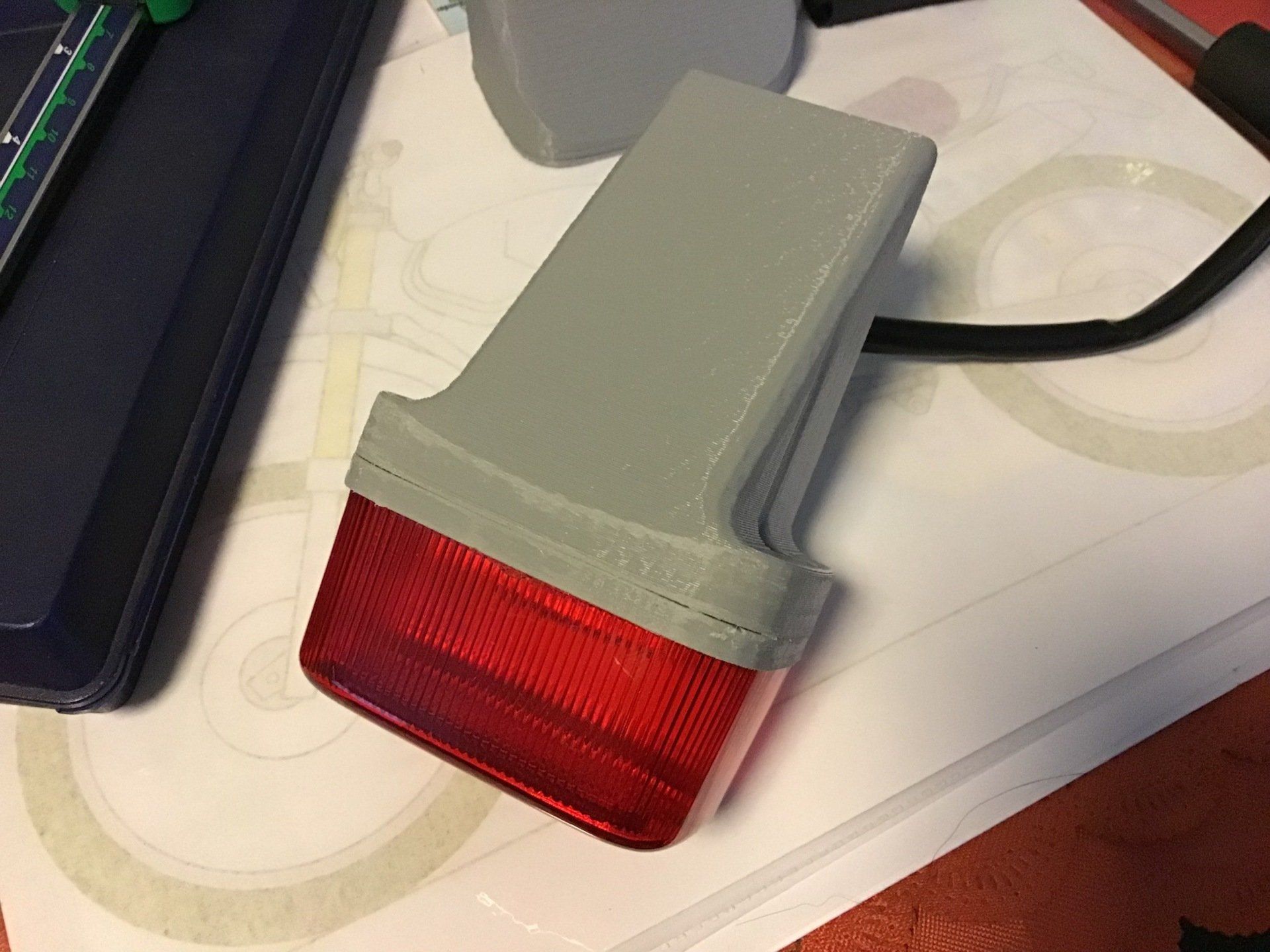
Hot off the 3D printer, the Mk1 version of the rear light.
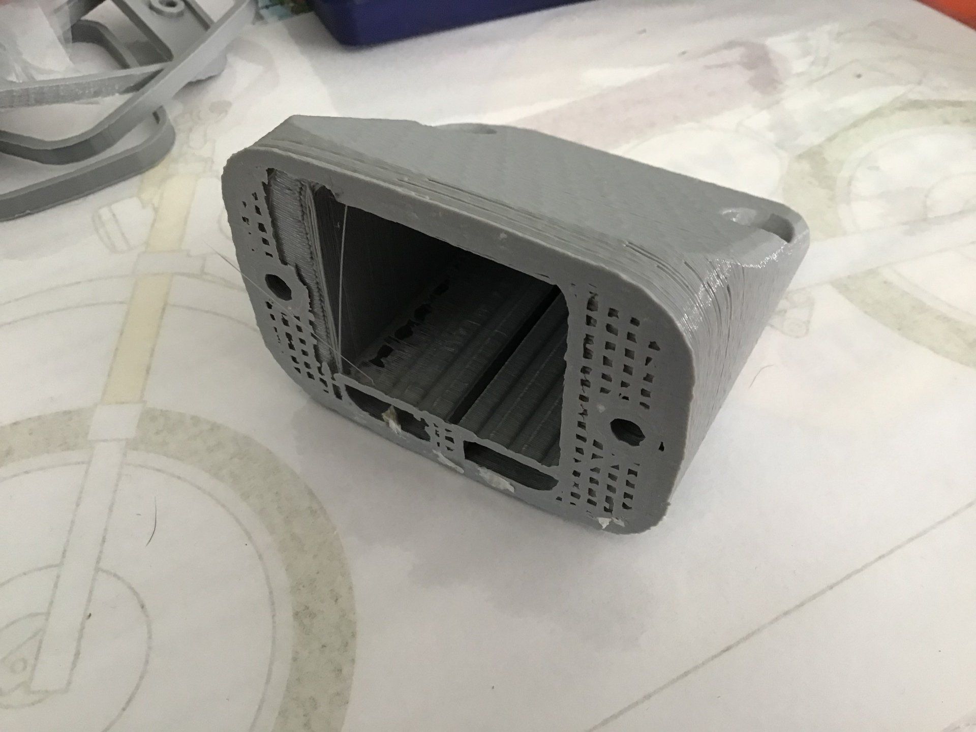
With a little bit of adjustment, the light fitting is installed (and working!)
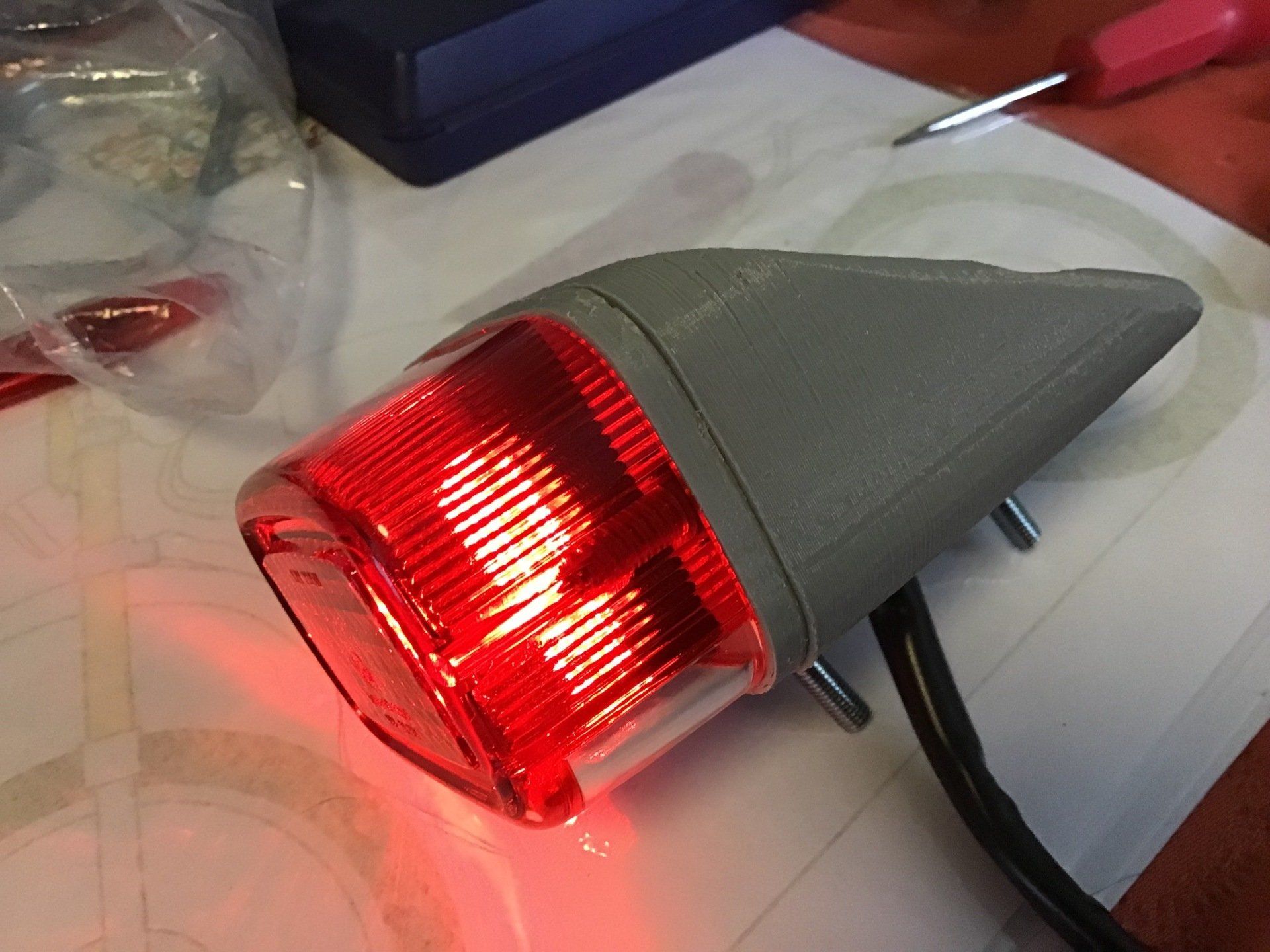
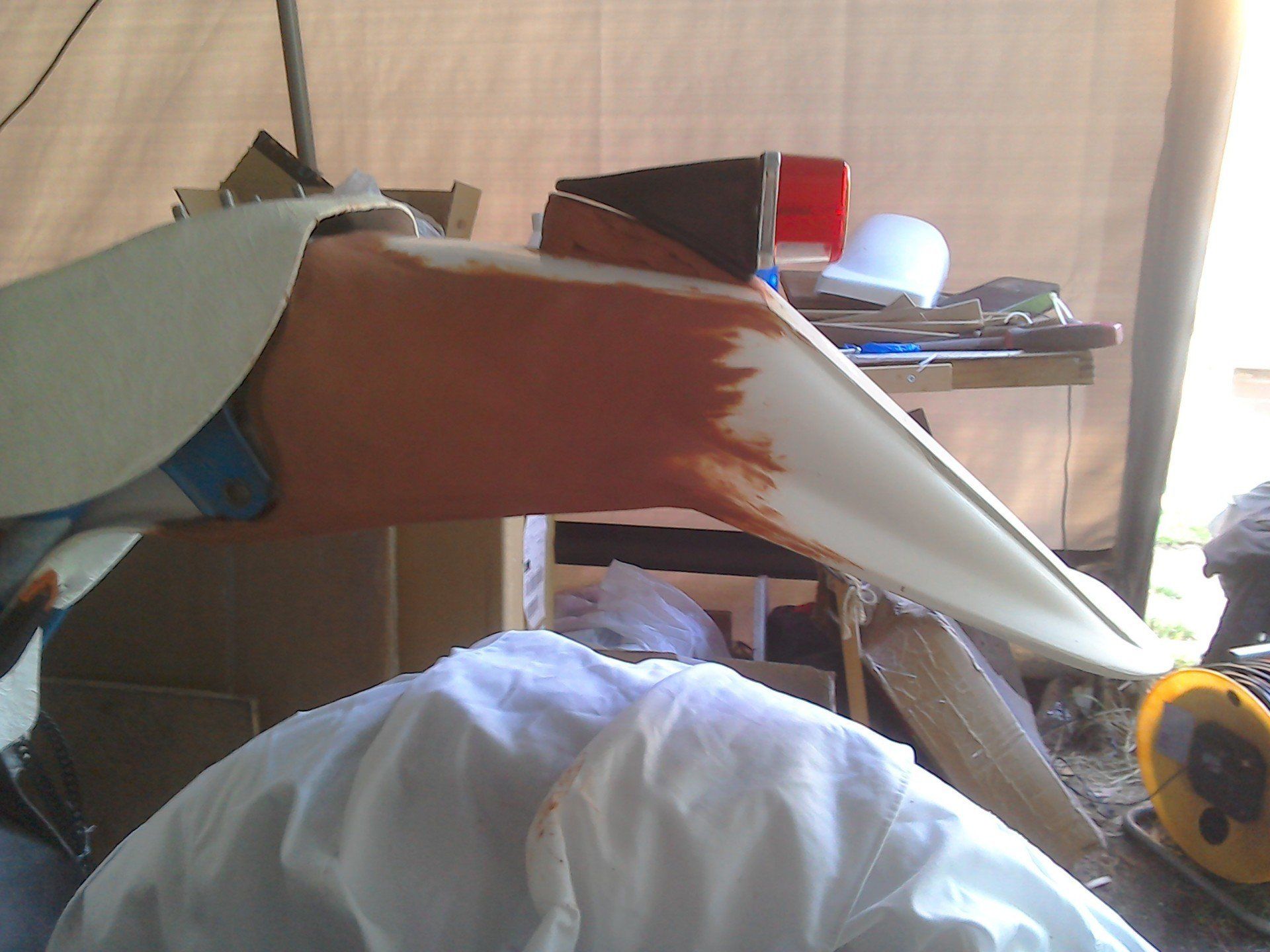
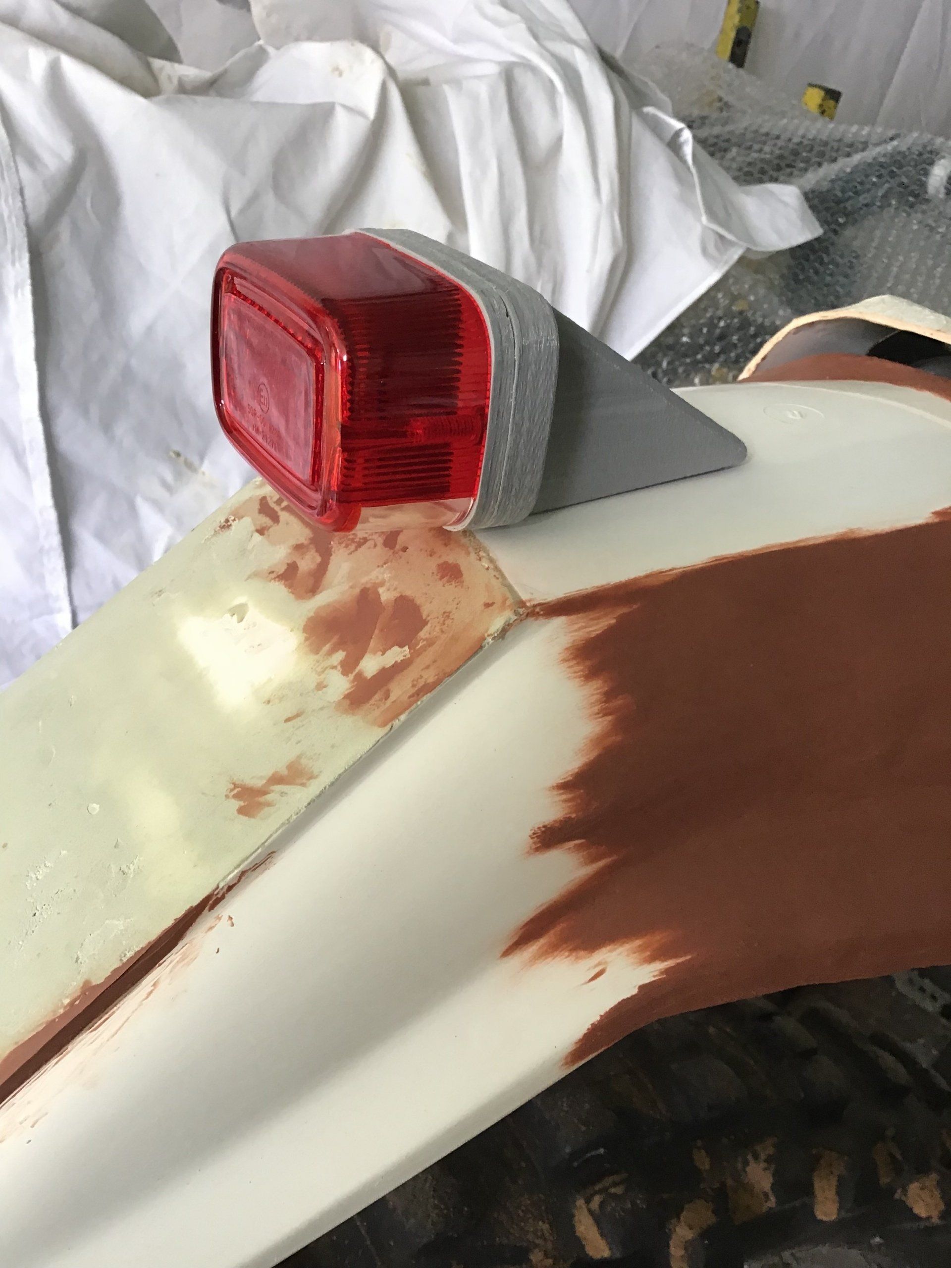
A quick trial fitting. It looks OK, the angular style works well with the equally angular style of the rear mudguard.
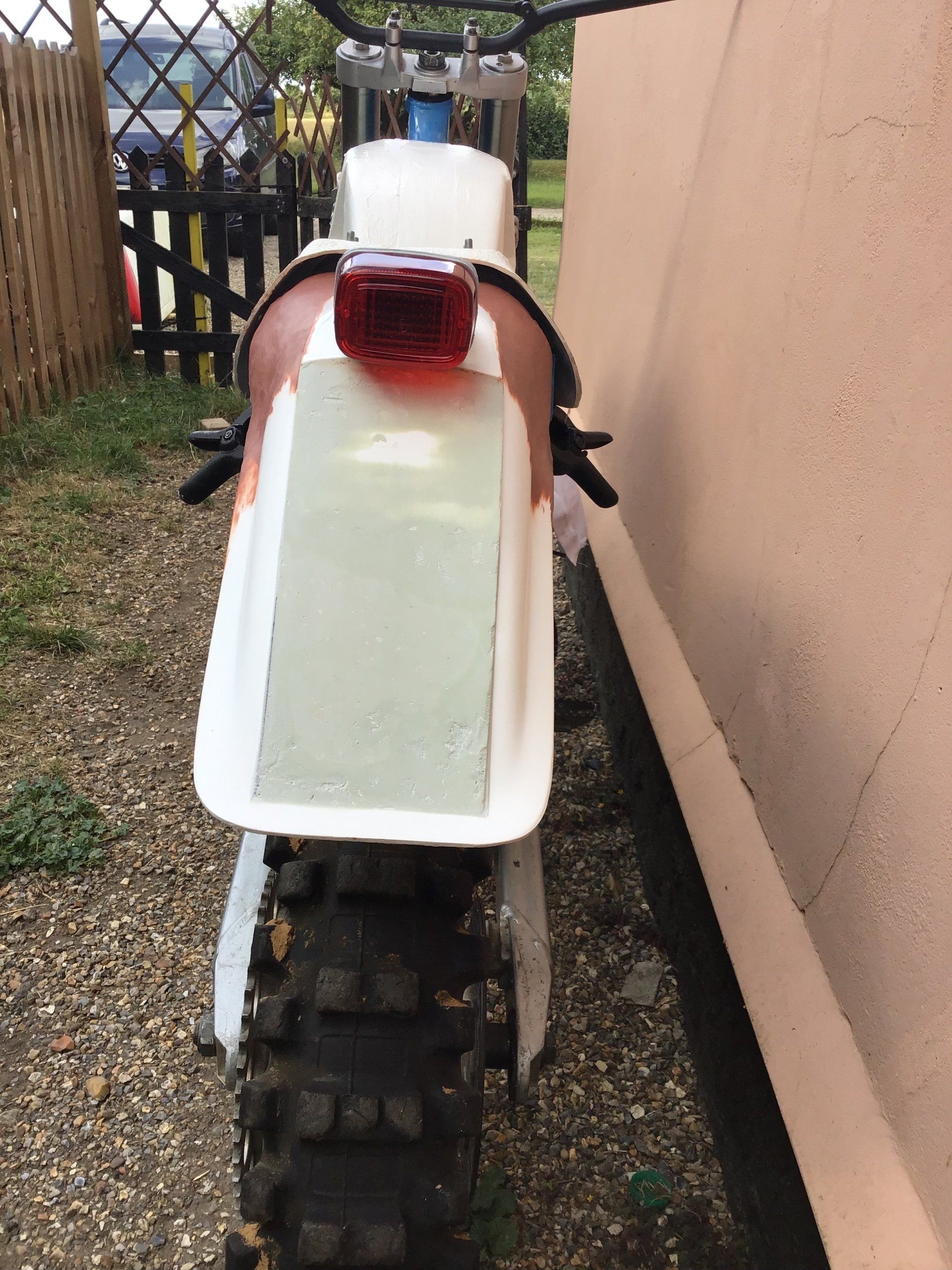
And a view from the rear... Light looks OK, but the clay restyling of the rear mudguard isn't symmetrical - yet!
Next up, the Mk2 version. This one's a bit slimmer and corrects a few of the defects of the Mk1.
Bottom view of the light. There are a few printing defects, not due to the 3D printer, it's more down to my poor 3D CAD editing skills. There may well be a Mk3 version, although this one could be sorted with a bit of filling and sanding.

A quick trial fitting on the bike. This print out has 0.3mm layers, so is quite rough. There's always a trade off between quality of print and printing time. There may be a Mk3 version on the cards. I haven't decided, yet...
This week's job was to start looking at side panels, so, once again, some drawing on photos of the bike was undertaken. Of the 5 or so options that I came up with, this one was the most popular.
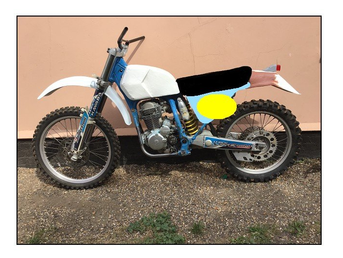
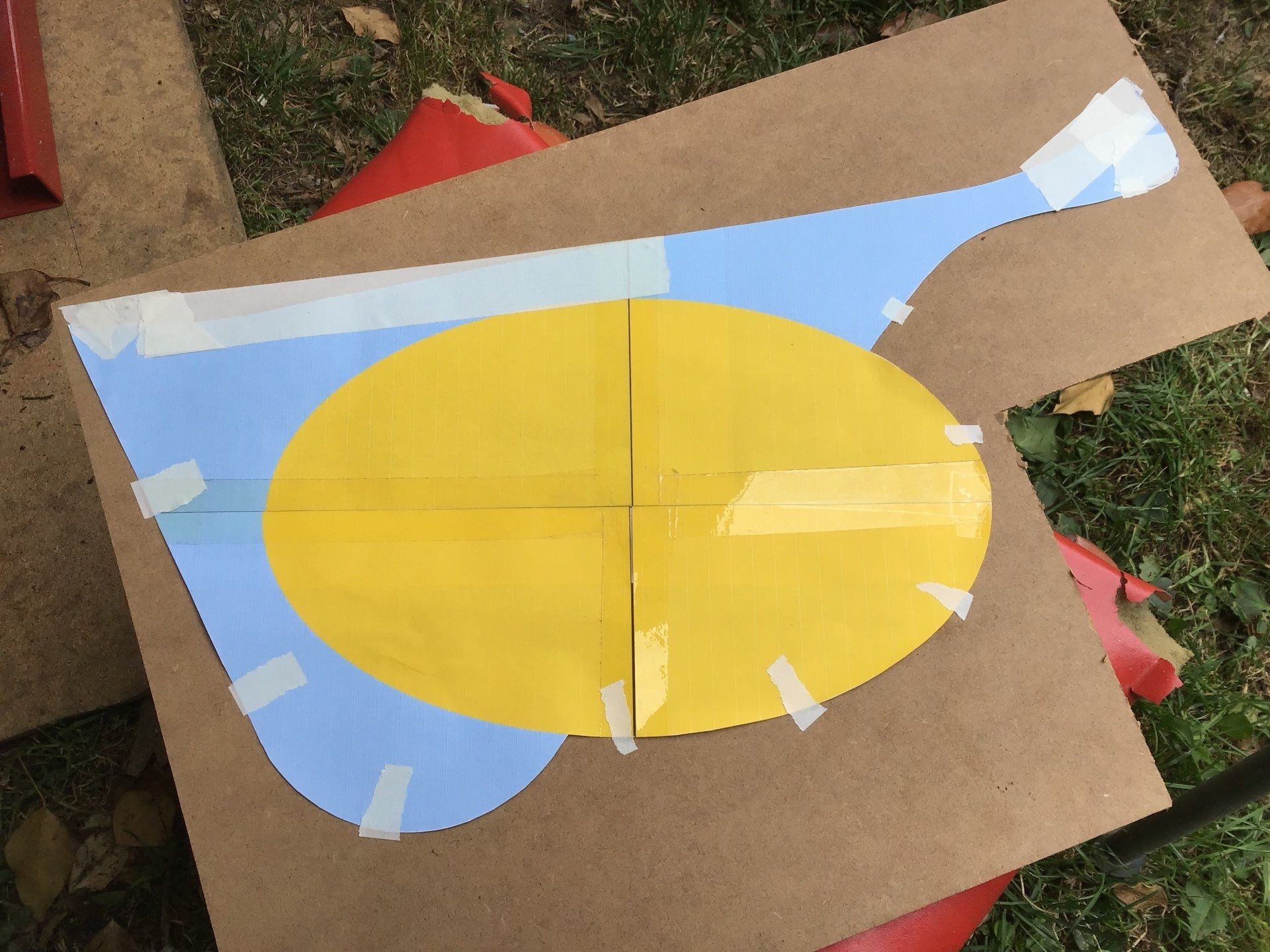
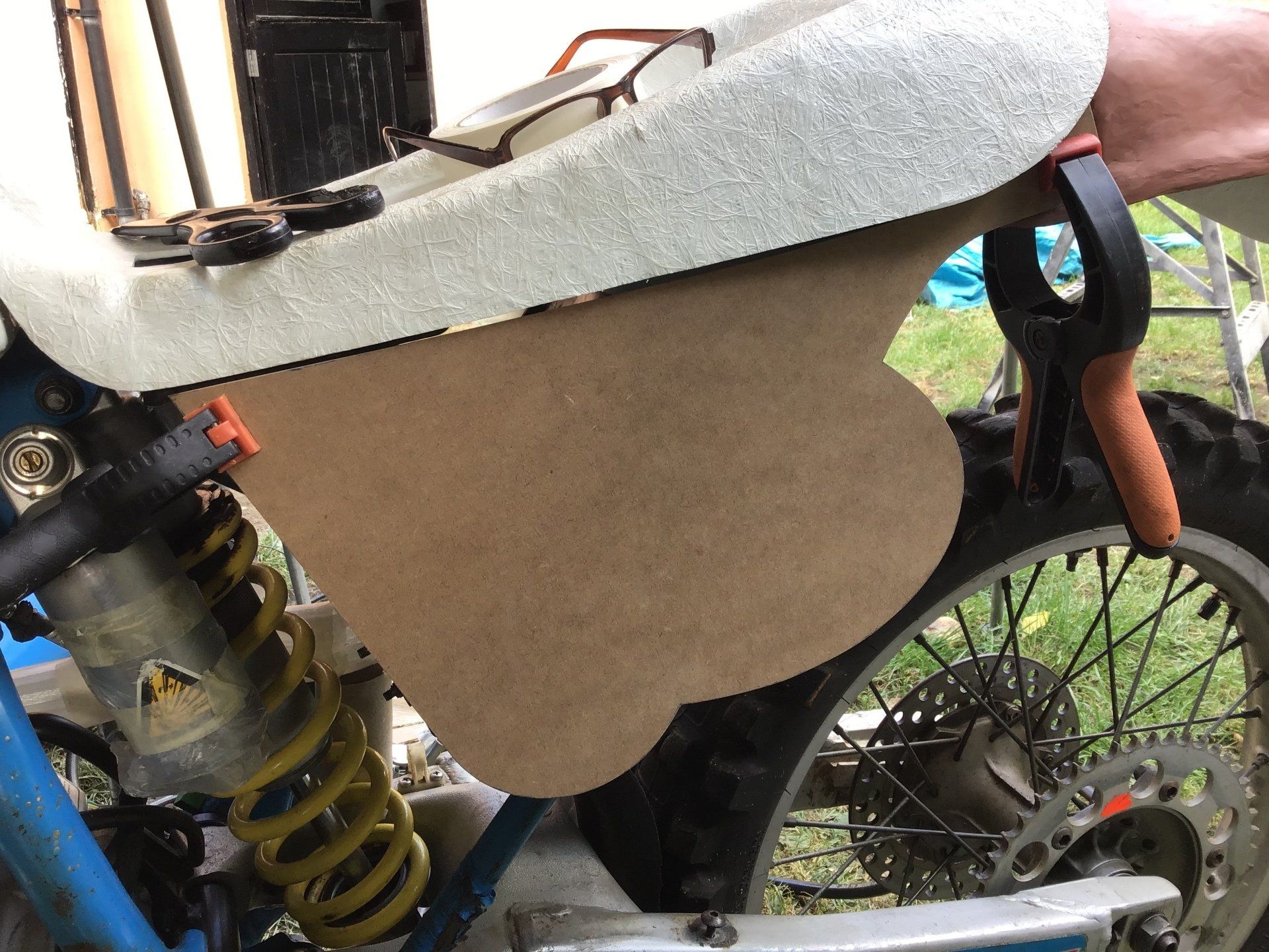
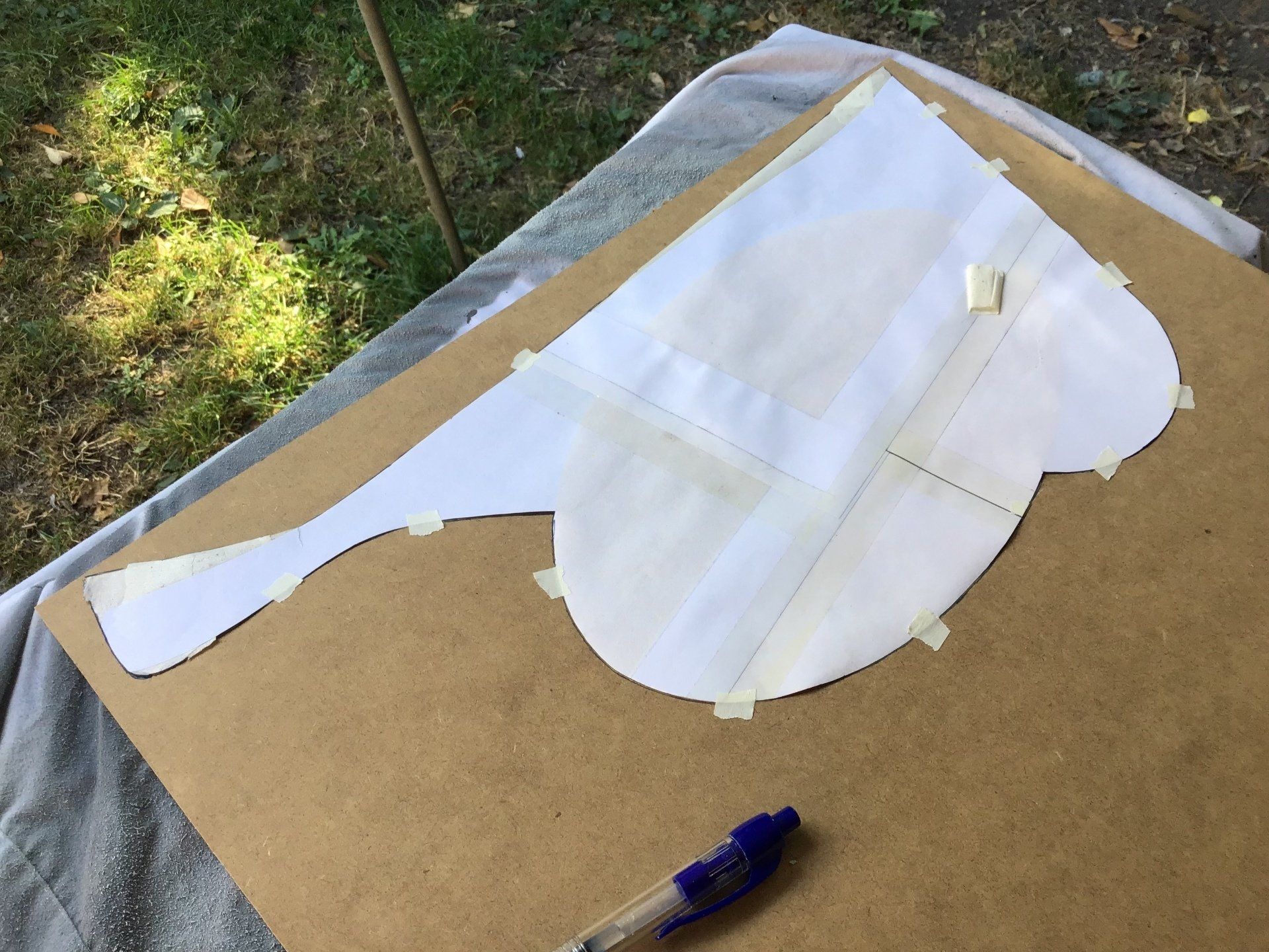
A full size paper template was printed and offered up to the bike to see what it looked like and how well it fitted.
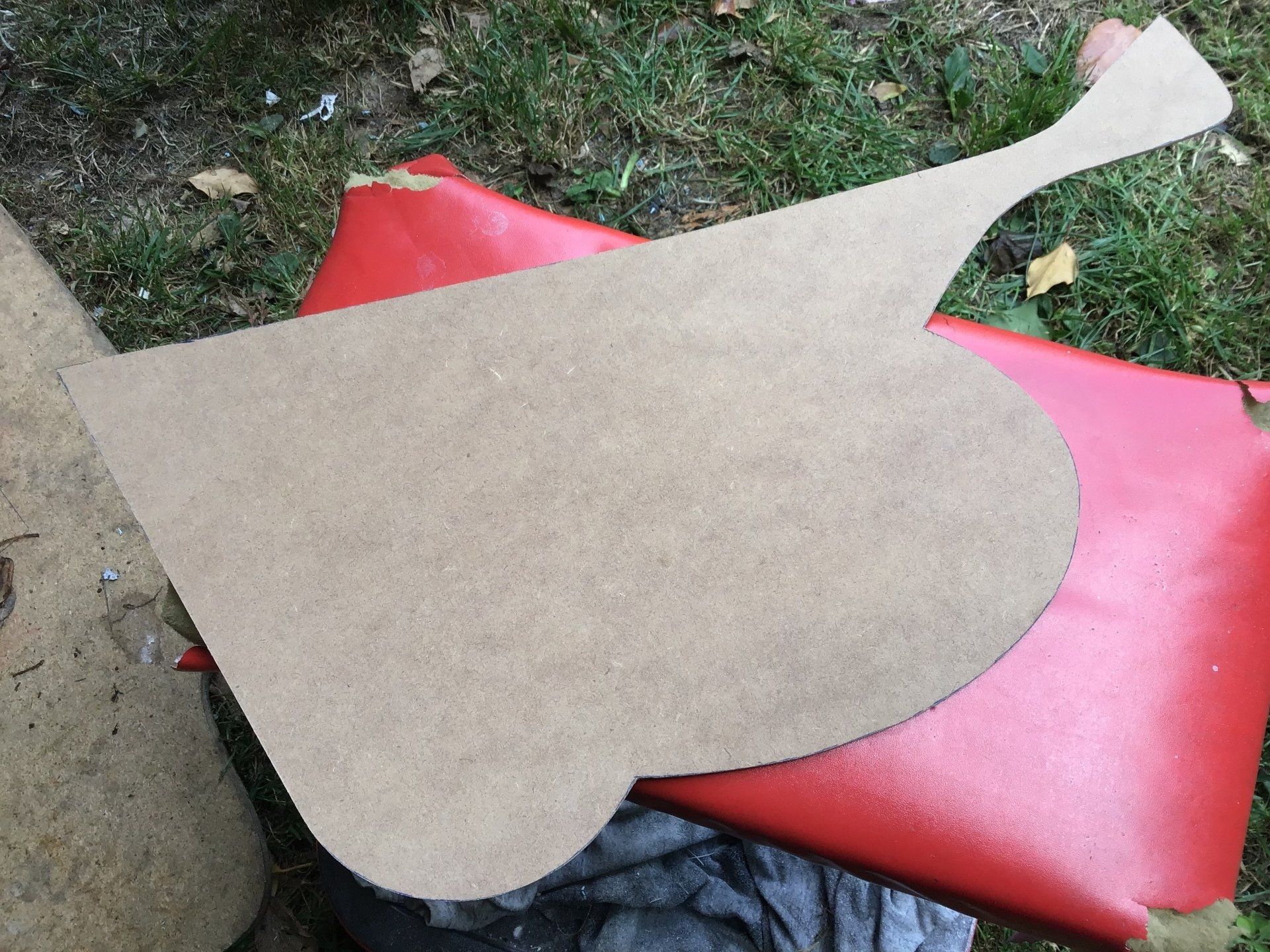
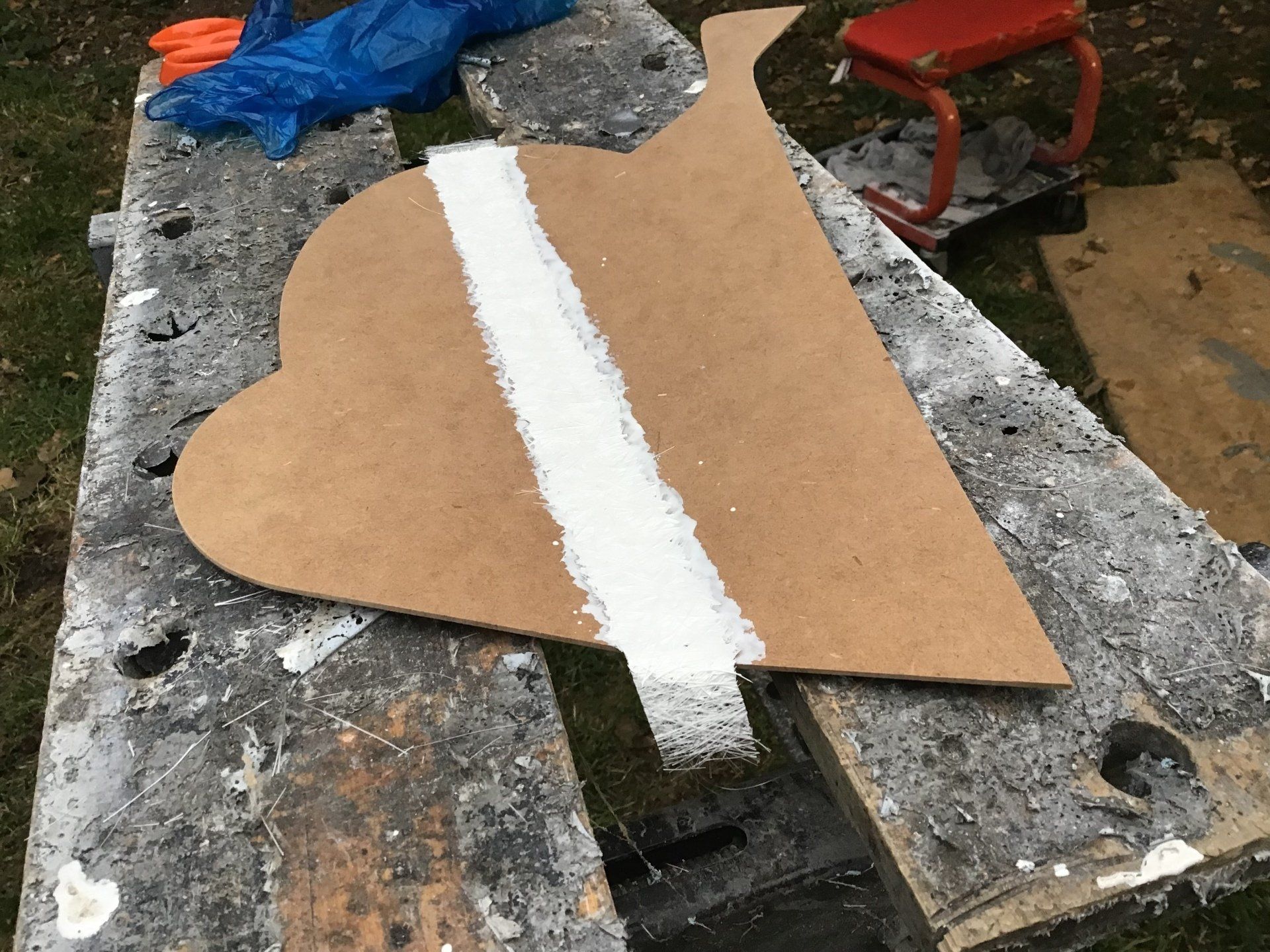
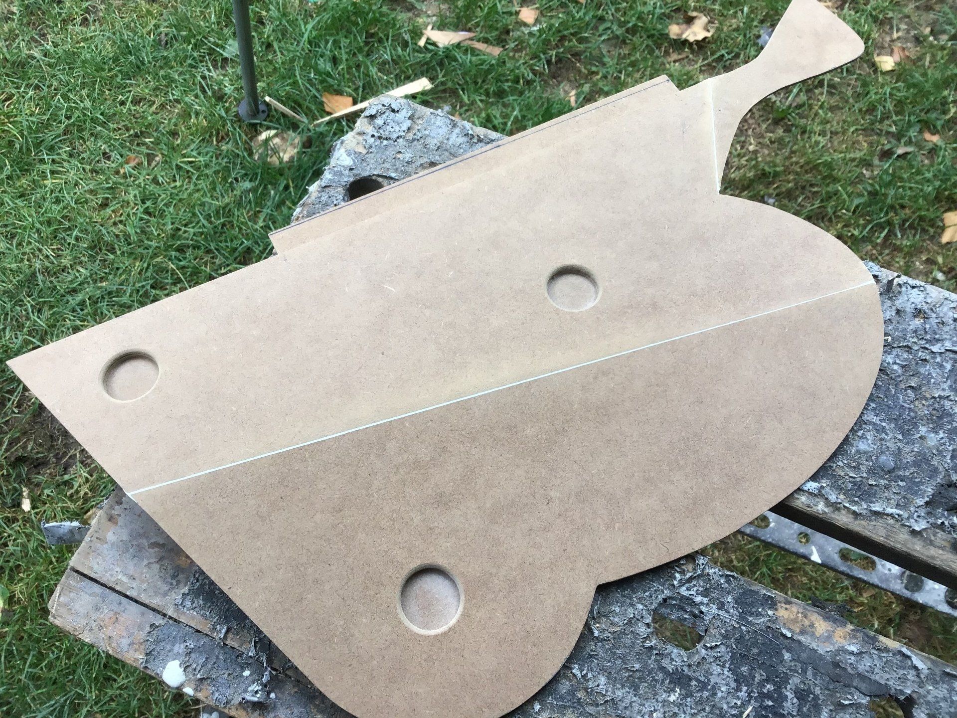
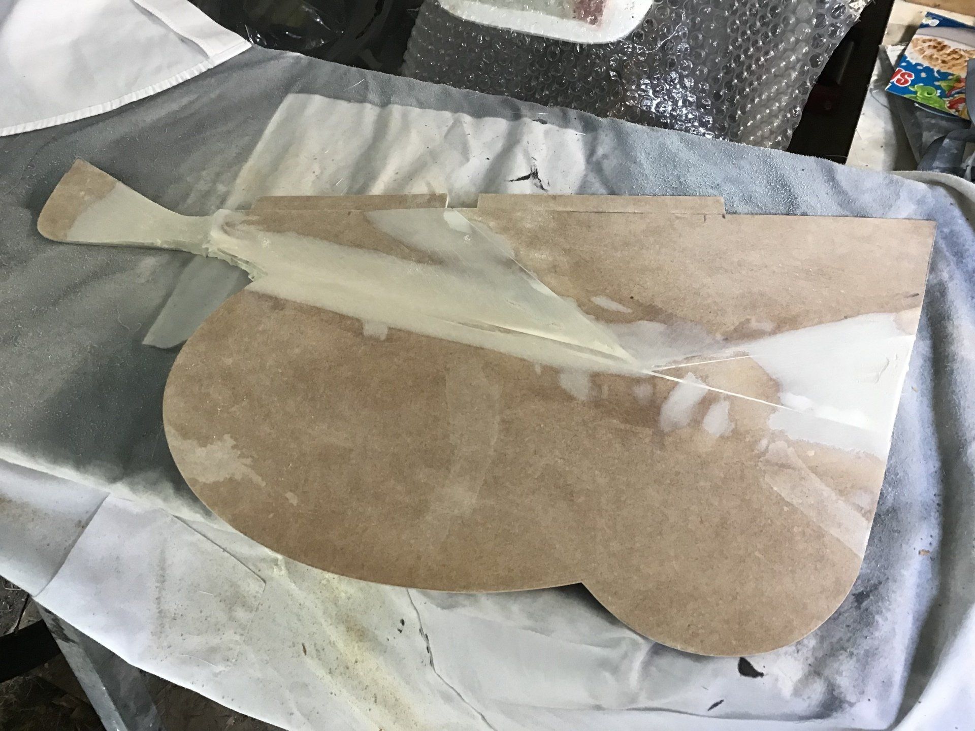
With some minor adjustments made to the design using some masking tape, this then became the template for a 2mm thick MDF version.
A standard wood saw was used to roughly hack away the excess, then it was finished to shape using a flap disc on the angle grinder. Wear a dust mask, the dust from MDF is not good for you.
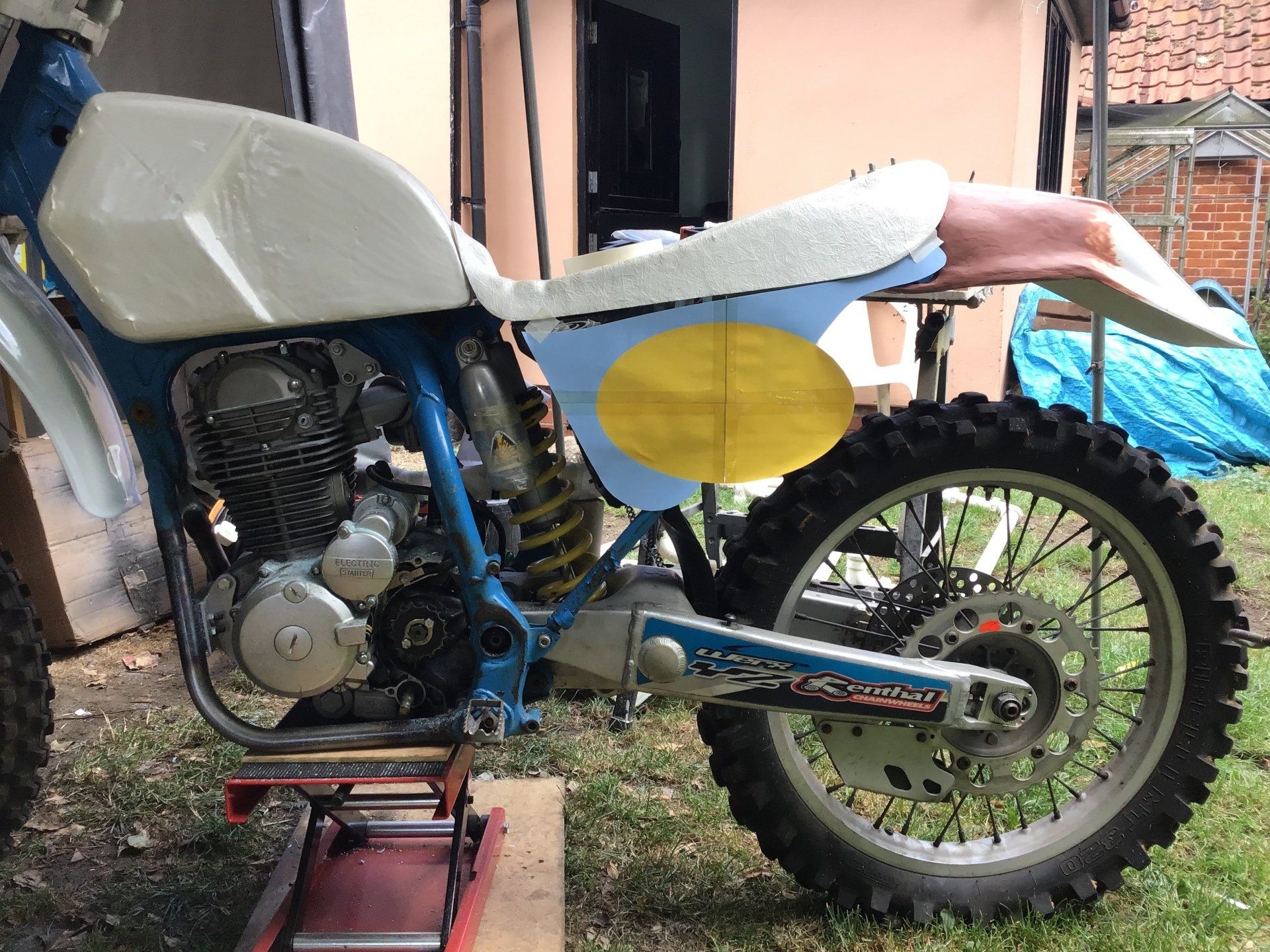
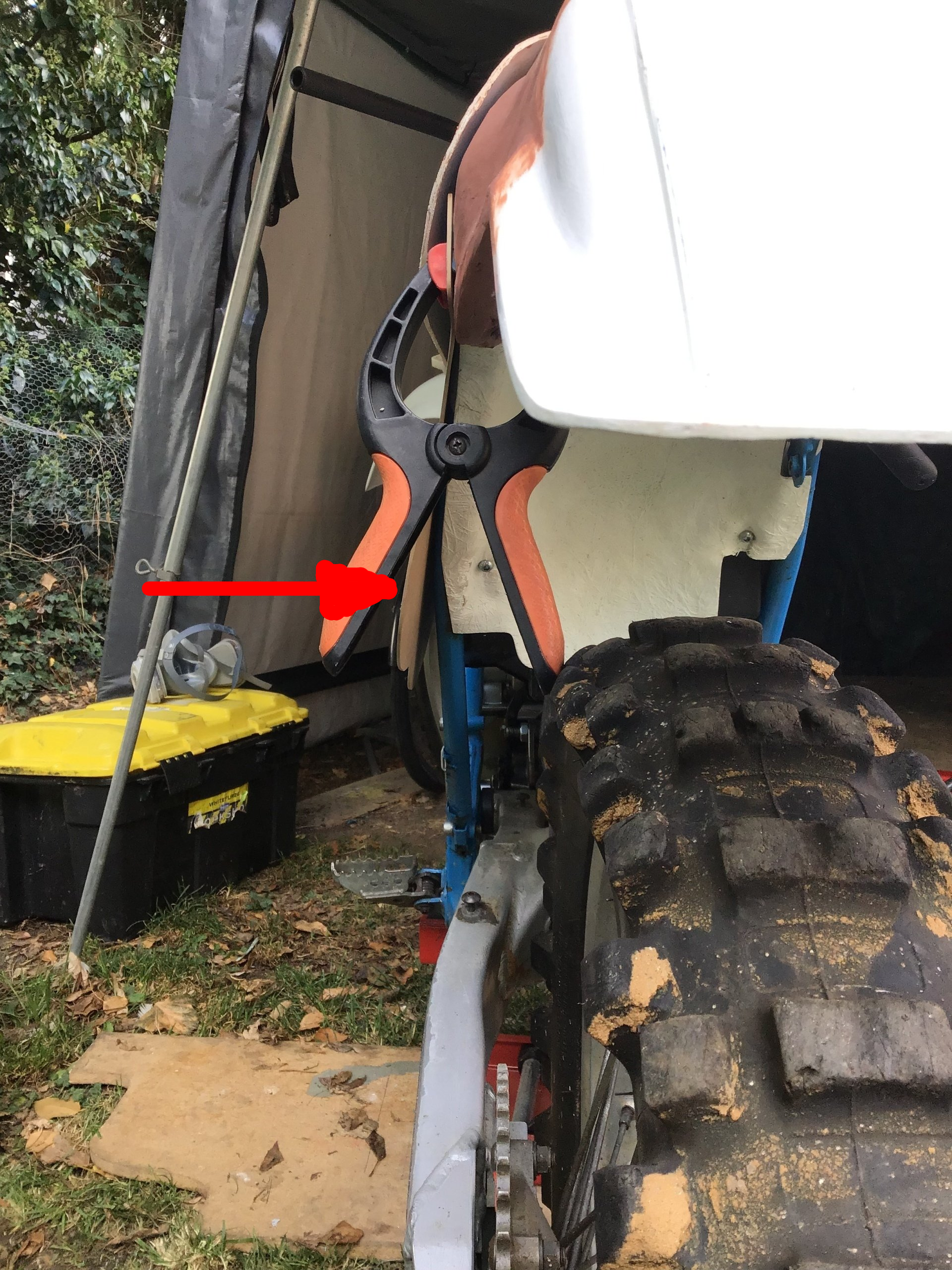
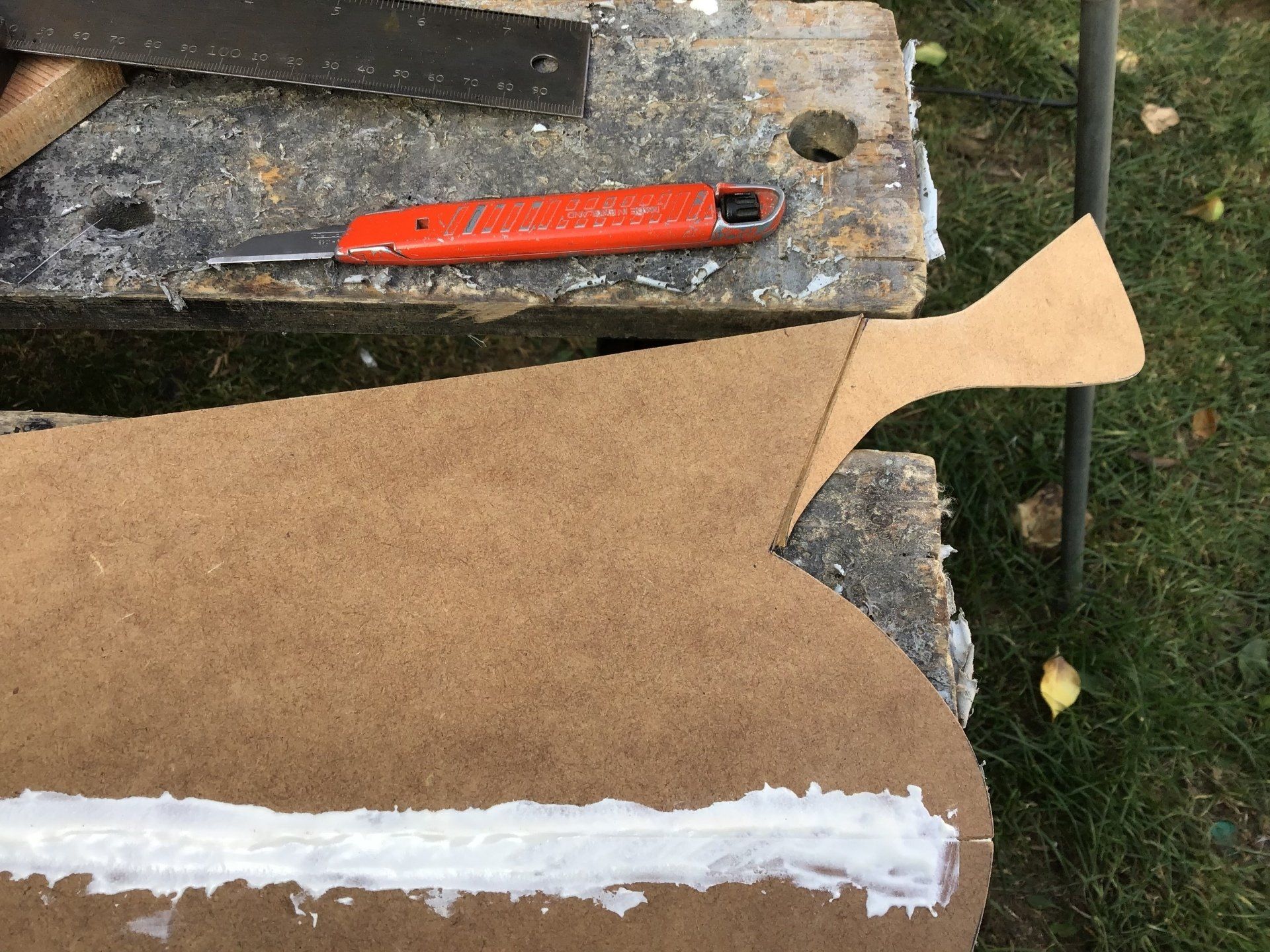
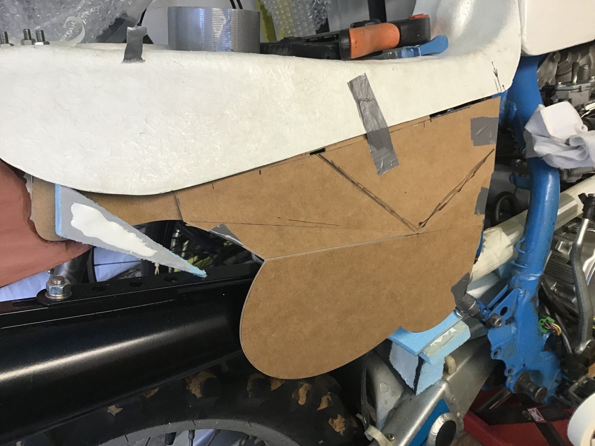
Trial fitting of the MDF side panel, it's about the right size, but not quite the right shape...
... the big red arrow marks where the panel needs to bend so that it hugs the frame rail.
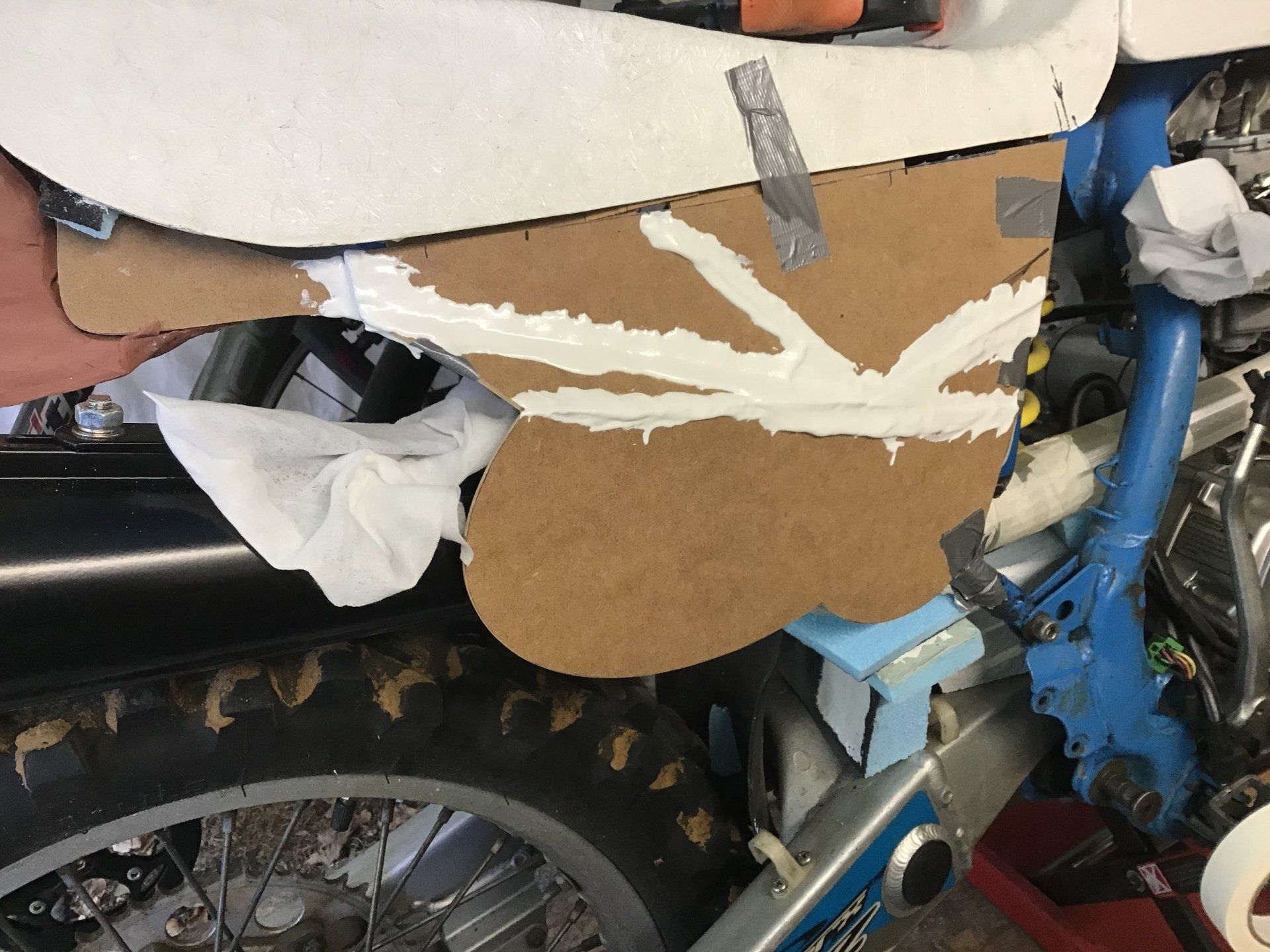
The panel has been cut in the required place and the two parts held together by tape, allowing the bottom to swing down to meet the frame rail.
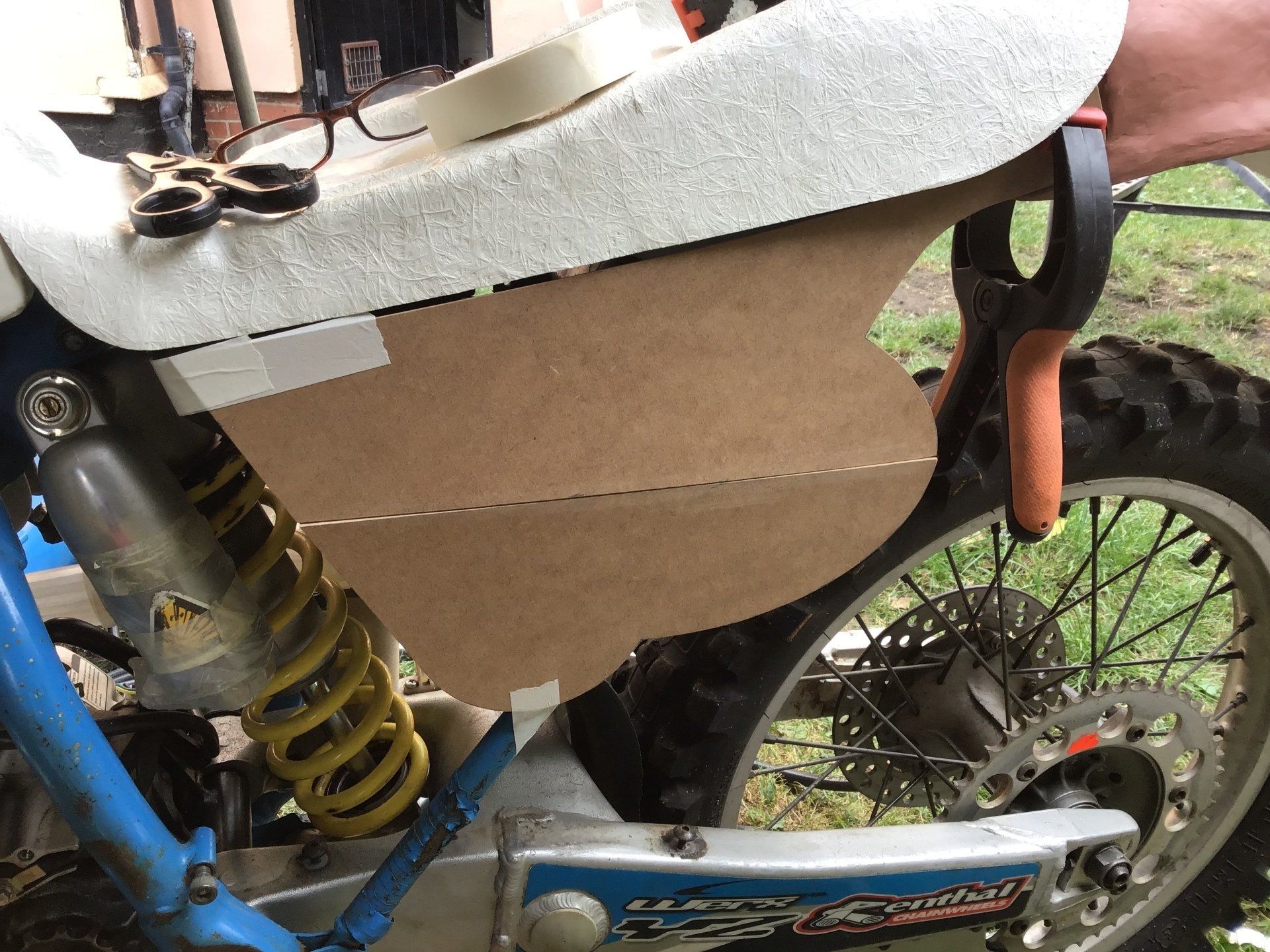
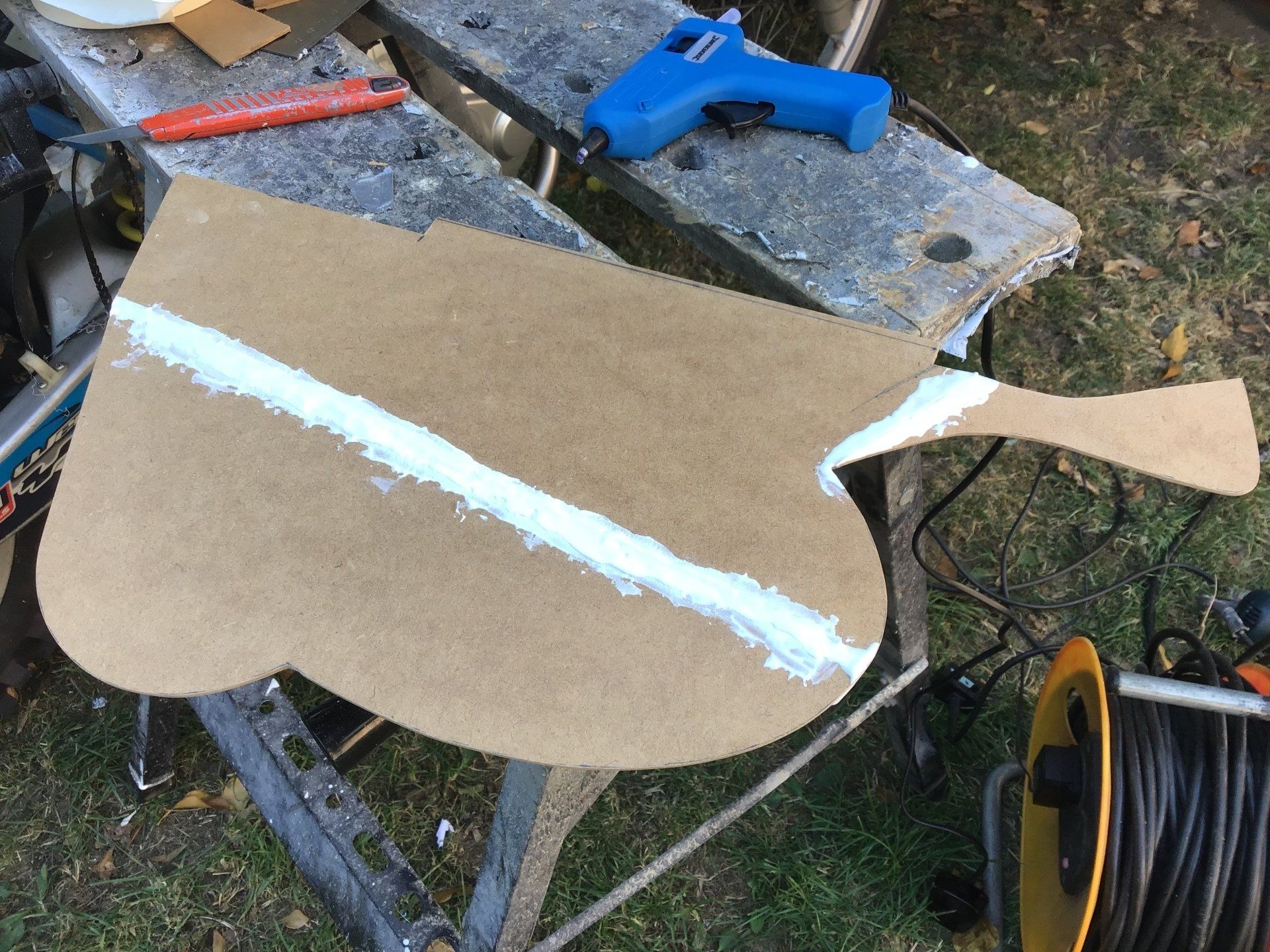
Using some extra pegs and masking tape, it's held in position whilst some laminating resin (thickened with talc) is used to stick it in place.
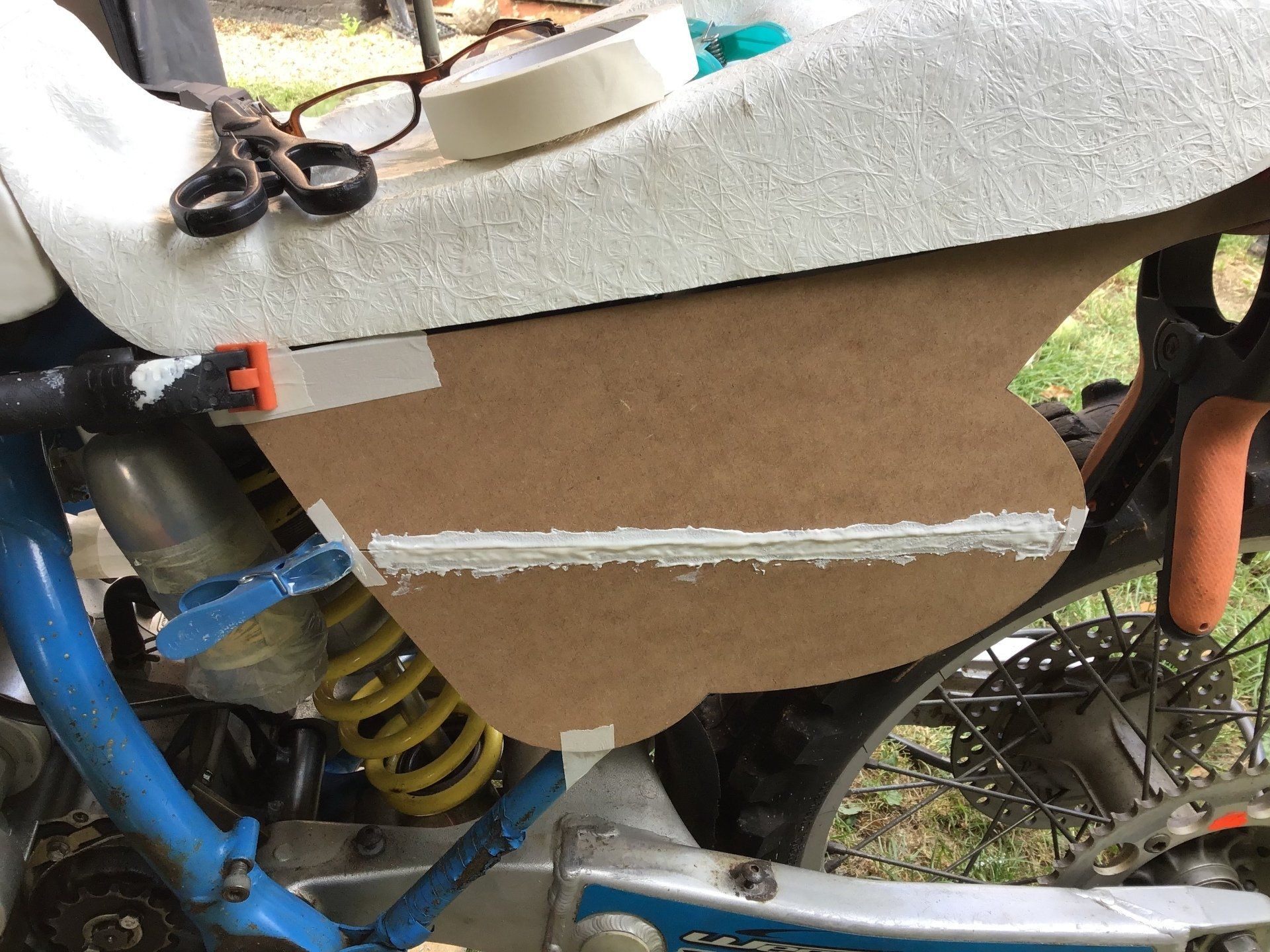
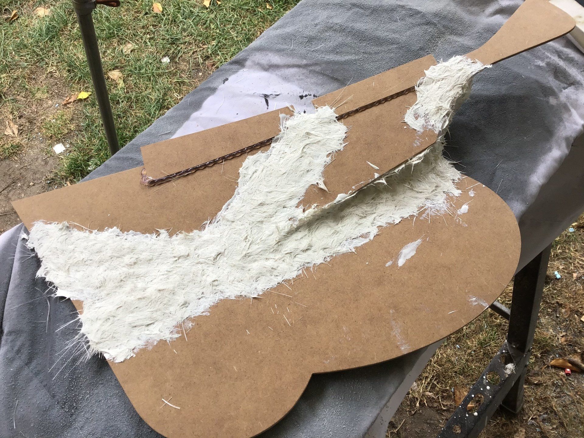
Once dry, a thin strip of chopped strand mat is added to the back to reinforce it.
Another little bend is required. This time I've chosen to score partly through the mdf, before bending to the required angle and sticking it in place as before.
Not a great photo, but a strip of mdf has been added using a glue gun along the top edge. This will sit underneath the edge of the seat and will help to locate the side panel and also be an added barrier to crud making its way into the airbox.
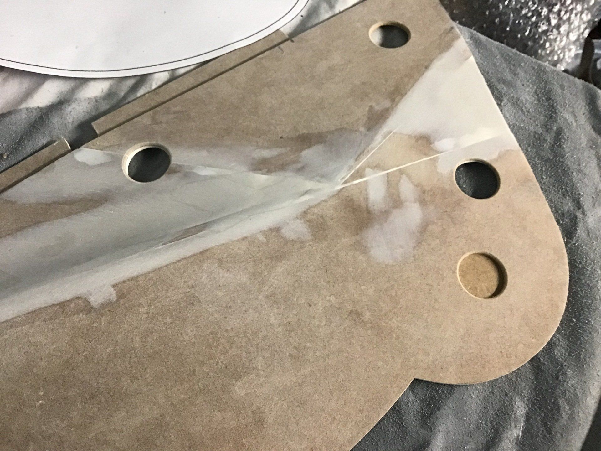
I want the fasteners to be recessed into the panel, so holes have been drilled and then blanked off to facilitate this.
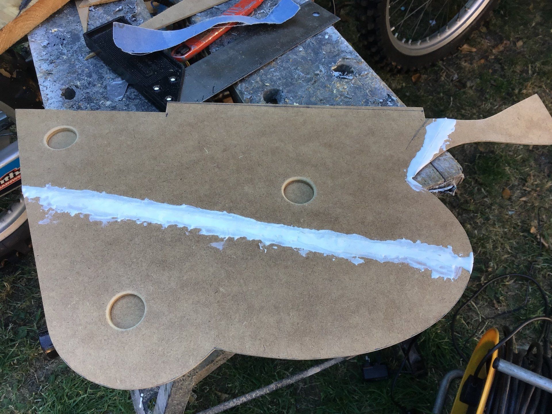
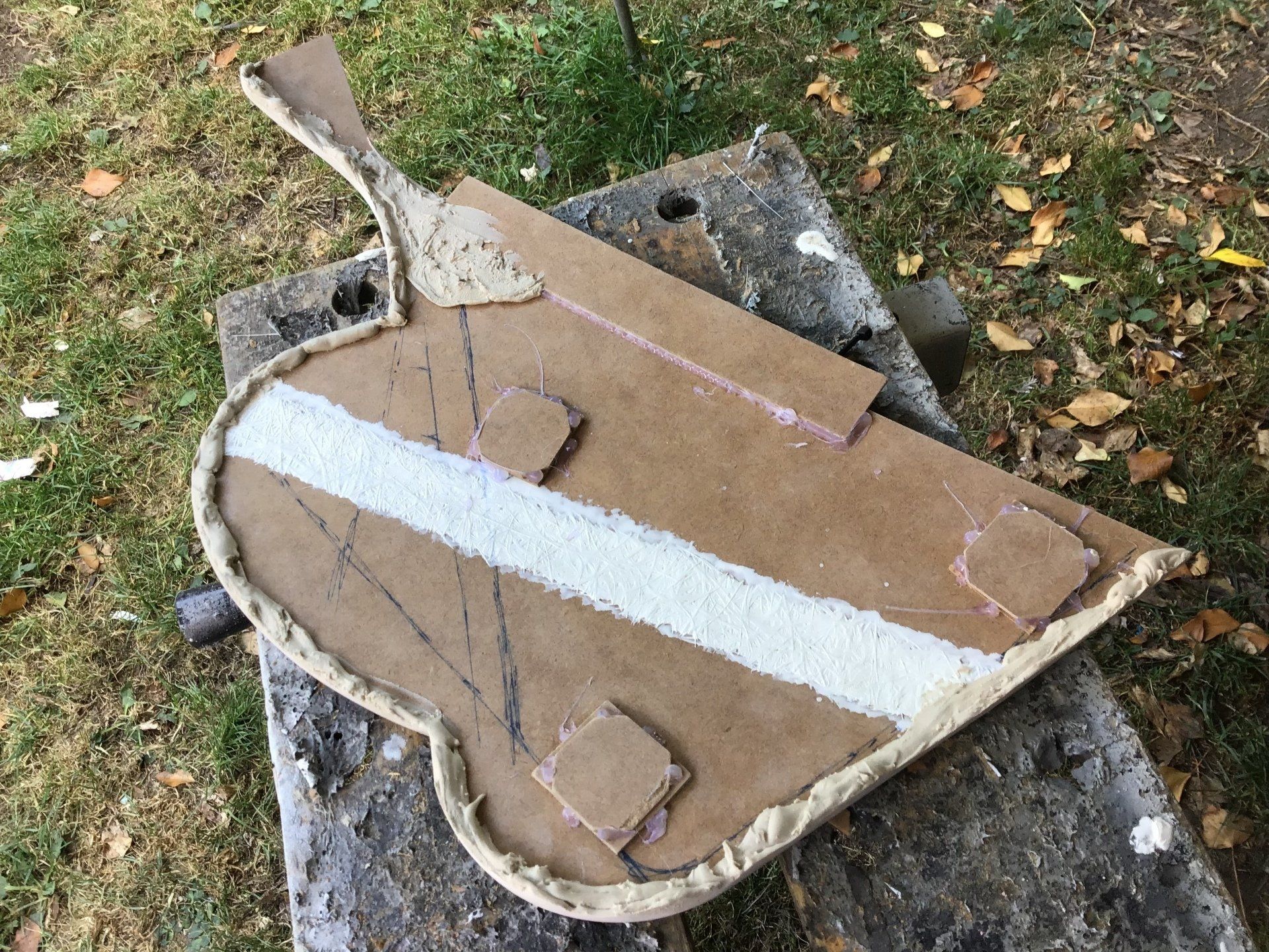
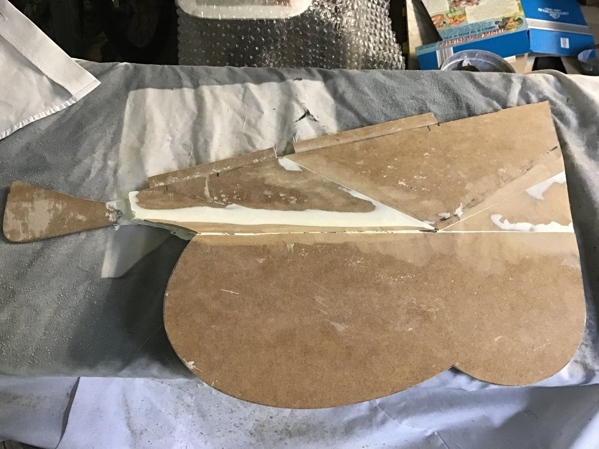
A back view of the panel, which gives a better view of the panel shape etc. It now needs to be sanded and painted and have a few more little details added, before it can be used as a pattern to make the finished fibreglass side panel.
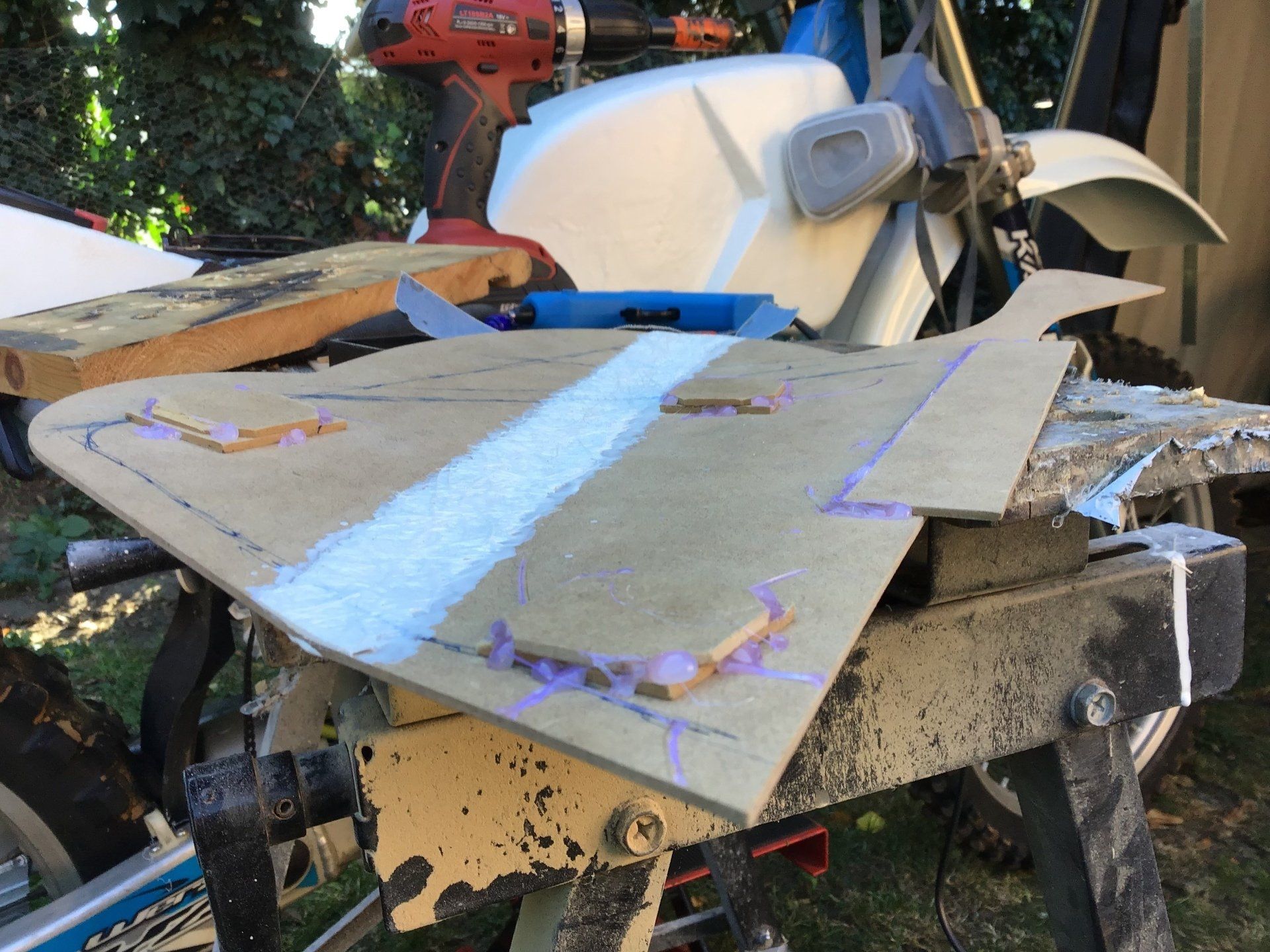
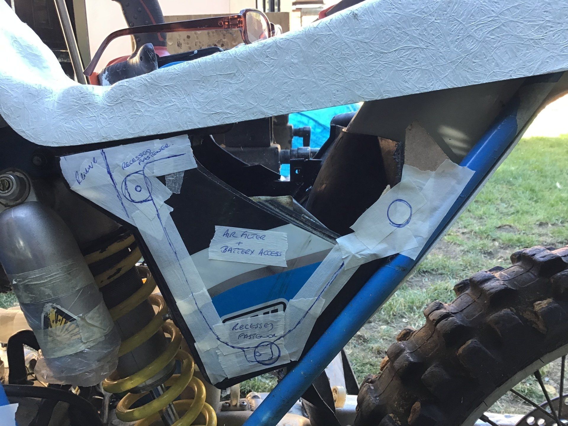
This side panel will also form the side of the airbox. The air filter and the battery need to fit into this space and be accessible by removing the side panel. There's lots of notes on the current airbox to remind me of the bits that need to be added, cut away or modified!
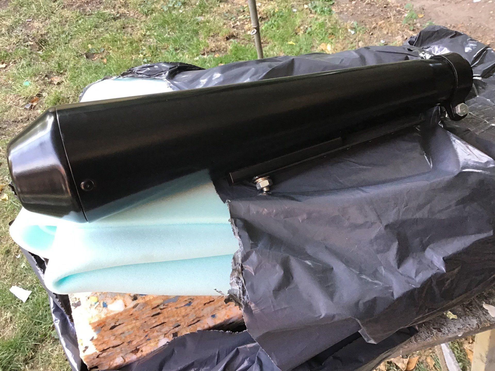
The other side panel will need to fit around the proposed exhaust system and silencer, so I've purchased the silencer that I'd like to use and some seat foam too for good measure.
Plenty to be getting on with, then...
If you'd like to see project updates during the week, then check out our new Instagram page.
Click on the icons below. The Facebook page is updated once a week, the Instagram usually three or four times a week.
If you'd like to see project updates during the week, then check out our new Instagram page.
Click on the icons below. The Facebook page is updated once a week, the Instagram usually three or four times a week.
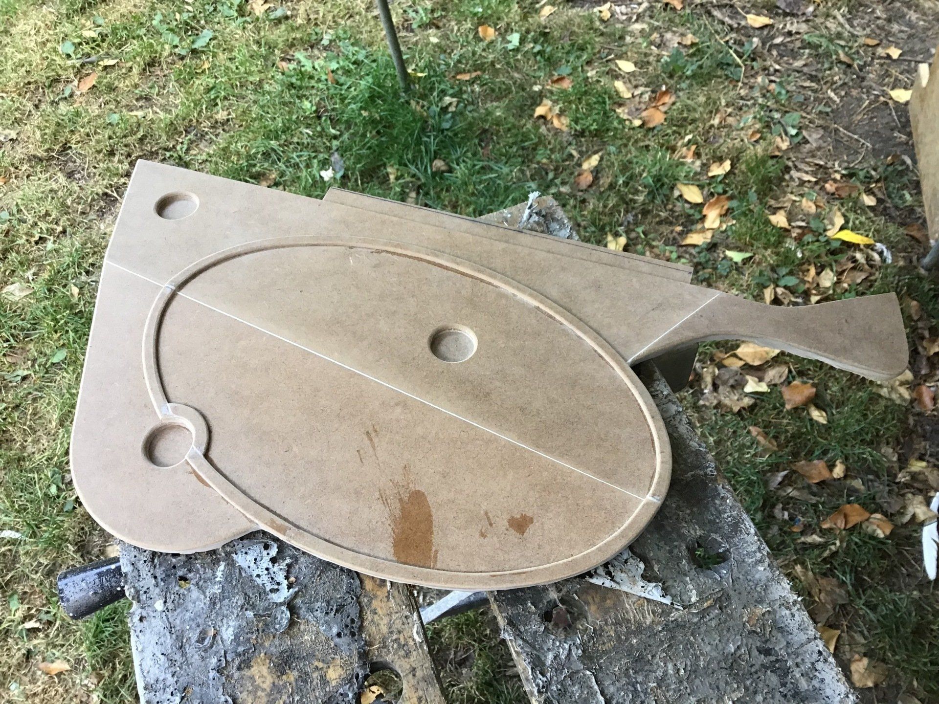
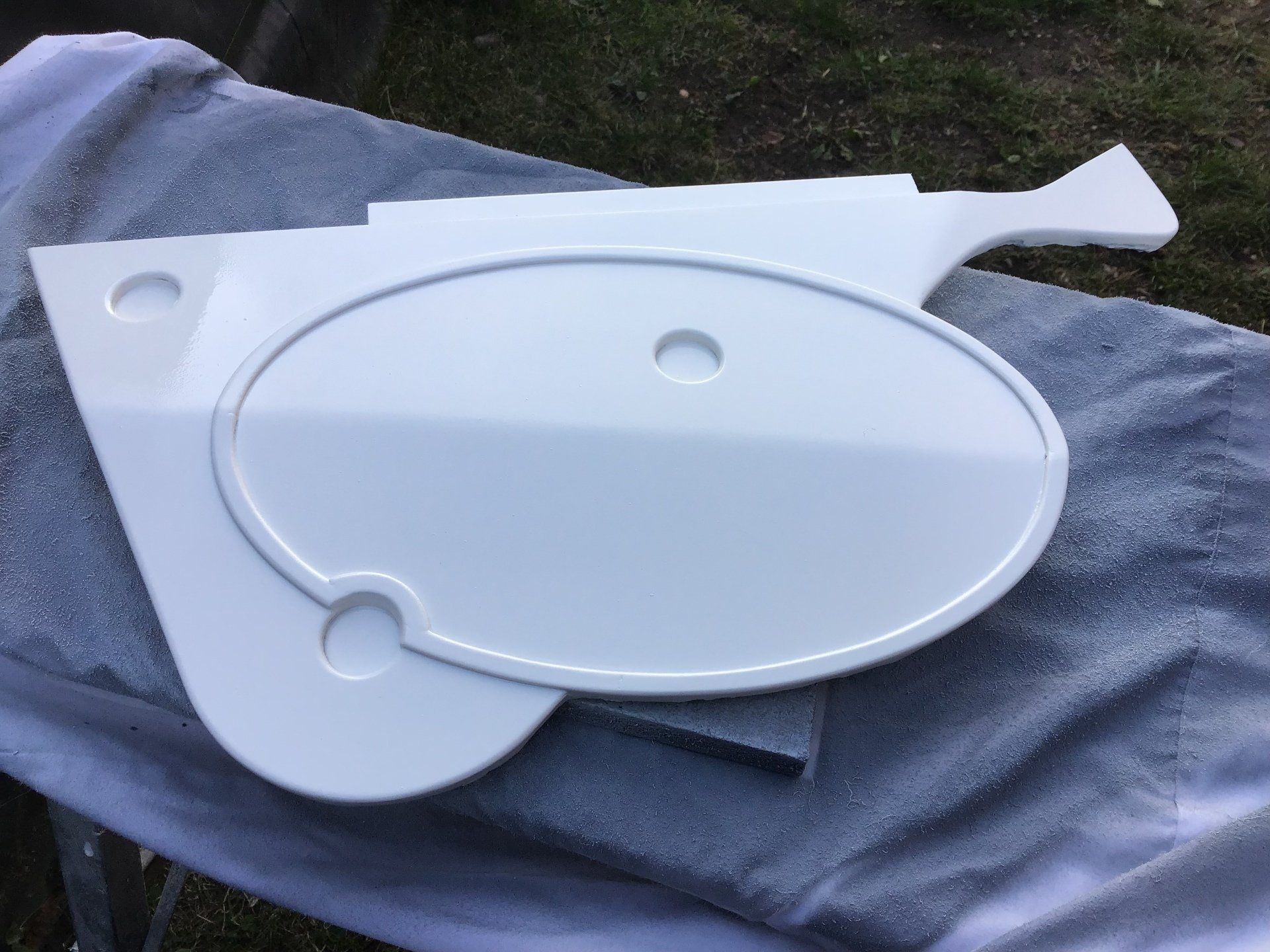
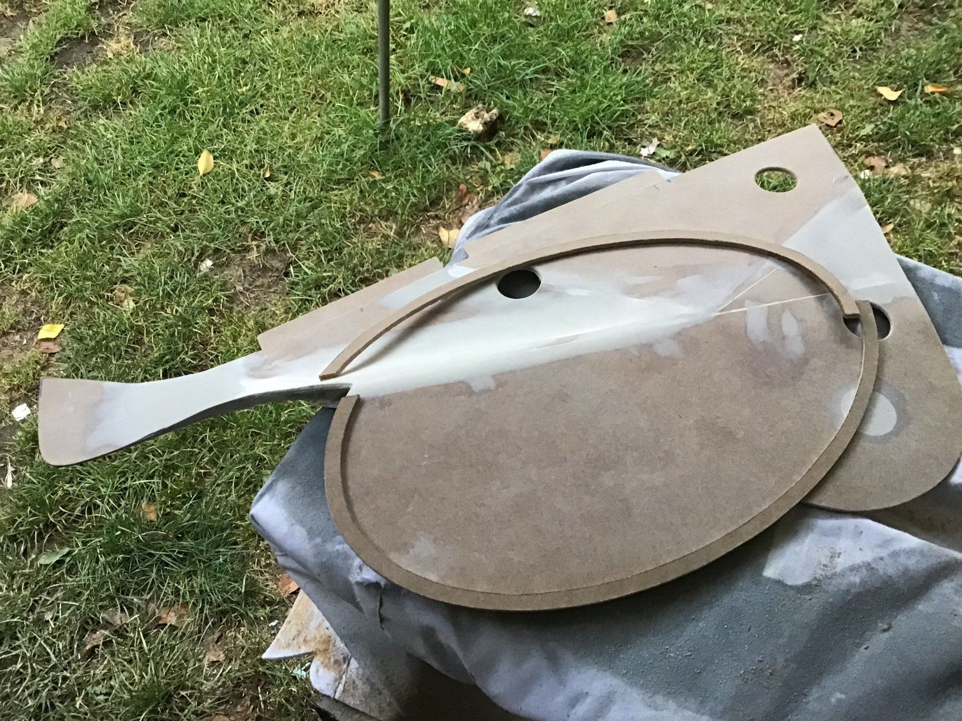
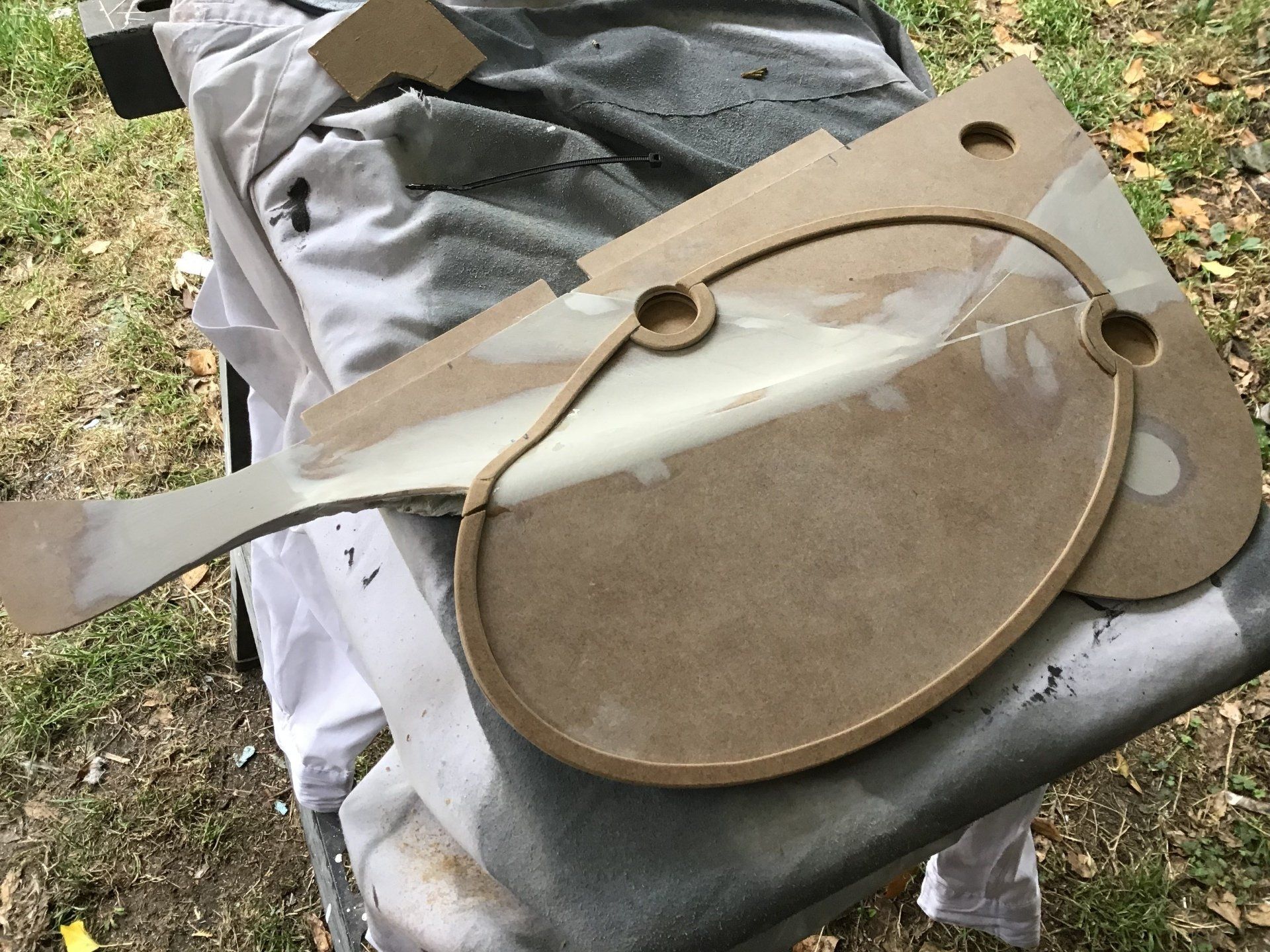
More side panel work. Here it is after the resin joins have been sanded...
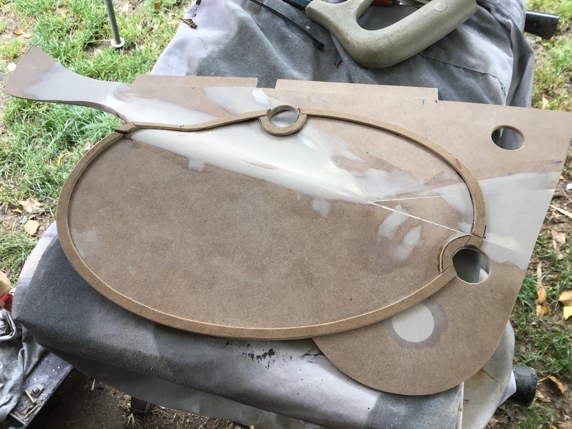
... and then with a bit of detail added around the number board. Cutting the oval from MDF was fiddly and it breaks easily - as you can see! Still, nothing a bit of super glue can't fix.
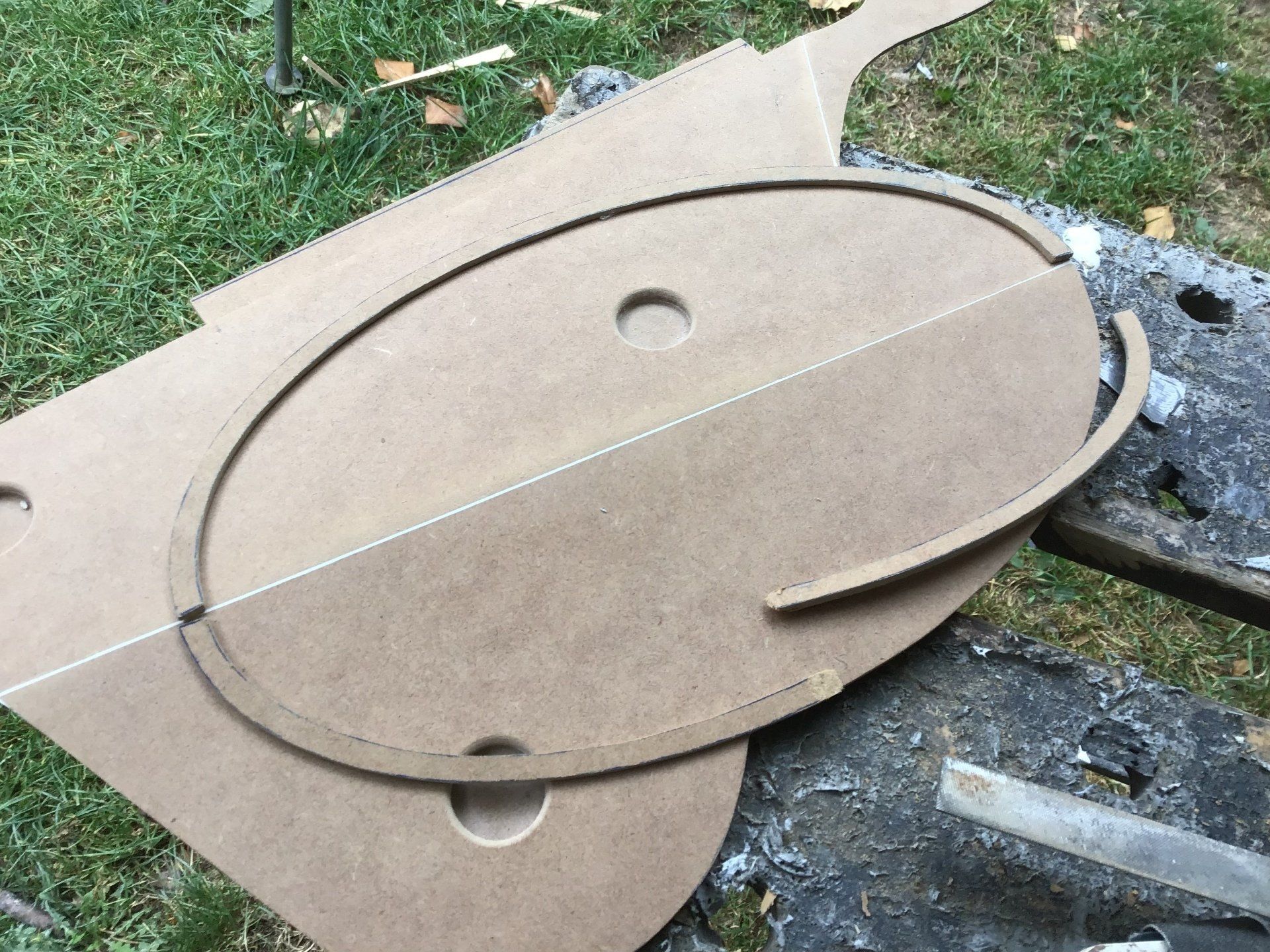
Finally, the raised oval is in place.
Body filler has been used to create an edge around the panel to make it a little more rigid, this will make life easier when it comes to making the mould.
Finally, here it is after the application of some primer and then top coat. I'm quite pleased with how it looks. I'm now a bit worried about taking a mould off it in case I mess it up. This has to be the best looking bit of 'wood work' I've ever managed!
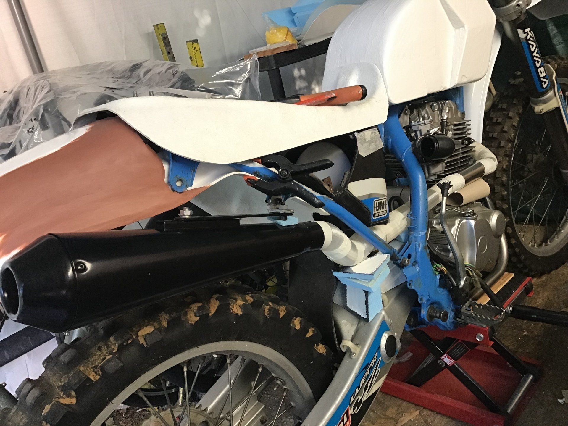
Now it's time to do the other side, so I've reinstated the 3D printed prototype exhaust and mounted the newly purchased rear silencer. It's a bodge job of ugly brackets and tape at the moment, but it is holding the exhaust in the right place. This side panel will need more shaping to accommodate the silencer - so that's going to be next week's job.
Starting point for this side panel is the same 2mm MDF and the same template as used before, just the other way around!
Once again, the 'cut and flop' technique has been used - in areas where a bend is required, the MDF is cut and the two pieces joined with tape on the back. This then allows the panel to flop into the required position. This side has to go around the silencer, so an extra bit of MDF has been added to bridge the gap.
Once everything is in place, it's fixed permanently using resin thickened with talc.
The back side has then been reinforced with chopped strand mat and resin. Several layers have been used as quite a lot of the MDF on the front will be ground down to make it more curvy.
The front side after some preliminary shaping.
Body filler has been added and sanded to smooth everything out.
Mounting holes machined. Notice the error at the bottom! The third hole was initially machined in the wrong place. It's been backed with some scrap MDF, and by the next picture it will all have been filled and sanded and we can pretend that it never happened.
The oval detail has been cut from 2mm MDF. This will be trickier to fit, there are two mounting holes and a curved surface to contend with.
Finally the oval detail is all stuck in place. It needs some filling, sanding and general tidying up.
The mounting holes have had their backs fitted and the oval detail has been tidied. Still some small gaps to fill before primer and paint, and then it's time to use these patterns to make the moulds for the real panels.
So, the next job is to get this painted, but while the paint is drying, I may look at the seat foam, or the airbox, haven't decided which, yet...